
Centrifugal fan for range hood

A centrifugal fan and range hood technology, which is applied to machines/engines, mechanical equipment, liquid fuel engines, etc., can solve the problems of increasing flow loss, polluting the impeller, etc., and achieve the effects of reducing eddy current, reducing pollution, and overcoming pressure.

Active Publication Date: 2016-09-21
NINGBO FOTILE KITCHEN WARE CO LTD
View PDF9 Cites 0 Cited by
  • Summary
  • Abstract
  • Description
  • Claims
  • Application Information

AI Technical Summary

Problems solved by technology

However, it is not suitable for use in range hoods. This is because the smoothness of the oil fume flowing in the leaf passage is more concerned about in the range hood. The flow in the blade path is smooth, and it can be thrown out of the impeller at one time as much as possible
In the existing double-arc blade profile, there are a lot of backflow and vortex between the blade flow channels. The pressure surface in the blade channel is higher than the suction surface pressure. Because the density and viscosity coefficient of the oil fume are higher than that of the air, the oil fume is easier to pass through. The pressure side flows to the suction side to form a vortex backflow, especially at the outlet, the airflow is blocked at the outlet and cannot go out, which not only increases the flow loss, but also makes the oil fume pollute the impeller

Method used


Image

  • Centrifugal fan for range hood
  • Centrifugal fan for range hood
  • Centrifugal fan for range hood

Examples


Embodiment Construction

[0023] The present invention will be further described in detail below in conjunction with the accompanying drawings and embodiments.

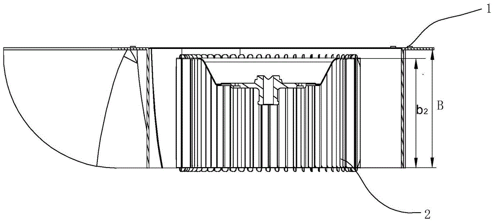
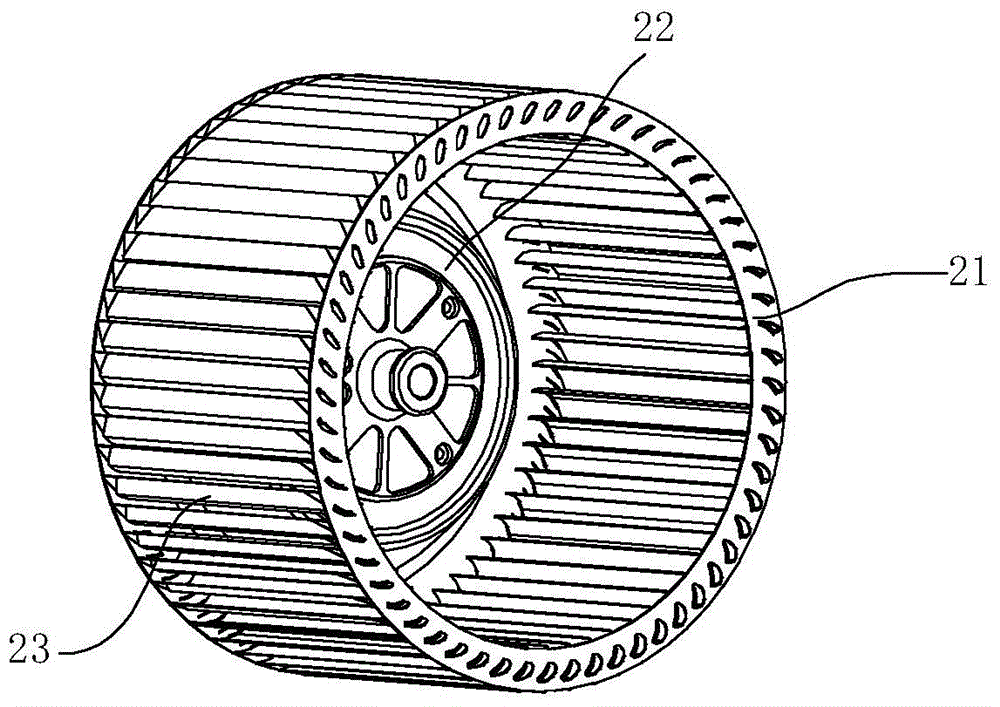
[0024] see figure 2 with image 3 , a centrifugal fan for a range hood, comprising a volute 1 and an impeller 2 arranged in the volute 1 .

[0025] The impeller 2 includes an end ring 21 , a disc 22 , and a plurality of blades 23 arranged between the end ring 21 and the disc 22 . The profile of the blade 23 is multi-diameter and multi-segment arc, which can make the air flow in the blade passage realize uniform acceleration movement, greatly reducing the flow separation or reducing the degree of flow separation in the blade passage.

[0026] see Figure 4 , the profile line C1 of the blade 23 includes two smoothly connected first circular arcs 231 at the inlet of the wind and second circular arcs 232 at the outlet of the wind, and the bending directions of the two circular arcs are consistent, wherein, R 3 is the radius of the tangent poi...


PUM


Abstract

The invention discloses a centrifugal fan for a range hood, which comprises a volute and an impeller arranged in the volute, the impeller includes a plurality of blades, and the profile of the blades includes a first circle smoothly connected at the entrance. arc and a second arc at the exit, said first arc having a radius R 1 , the central angle is α 1 , the radius of the second arc is R 2 , the central angle is α 2 , characterized in that the ratio of the radius of the first arc to the second arc is 3.5≤R 2 / R 1 ≤4, the central angle of the first arc is 85°≤α 1 ≤90°. Select the more reasonable radius and central angle parameters of the two arcs of the blade profile, so that the degree of shrinkage at the outlet of the blade and the narrow length of the blade are larger, the speed of the impeller outlet is larger, and the vortex in the blade channel is less, so as to better adapt to The application environment of the range hood makes it easier for the fumes to be thrown out of the impeller, and there is less eddy current inside the fan.

Description

technical field [0001] The invention relates to a range hood, in particular to a centrifugal fan of the range hood. Background technique [0002] The range hood has become one of the indispensable kitchen appliances in modern families. The commonly used range hood is usually equipped with a fan casing on the fume collecting hood, and the fan casing is equipped with a volute, an impeller and a motor driving the impeller. centrifugal fan. [0003] At present, the blades of the commonly used multi-blade centrifugal fan impellers are usually single-arc-shaped. The single-arc shape has the advantages of compact structure, high pressure coefficient, large flow coefficient and low noise, and is widely used in many ventilation devices. , electronic equipment and air conditioning systems and other occasions. However, due to the relatively large width of the impeller of the multi-blade centrifugal fan, the inlet airflow is unevenly distributed along the axial direction. The pressur...

Claims


Application Information

Patent Timeline
Patent Type & Authority Patents(China)
IPC IPC(8): F04D29/30F04D29/28F04D29/42
Inventor 刘逸余丙松俞辉茅忠群诸永定刘戈
Owner NINGBO FOTILE KITCHEN WARE CO LTD
Learn More