Non-contact high-precision calibration method of robot base coordinate system and its application

A technology of base coordinate system and calibration method, which is applied in the direction of instruments, optical devices, measuring devices, etc., can solve the problems of cumbersome operation, time-consuming, uncontrollable, etc.

Active Publication Date: 2016-11-30
SHANGHAI MITSUBISHI ELEVATOR CO LTD
View PDF10 Cites 0 Cited by
  • Summary
  • Abstract
  • Description
  • Claims
  • Application Information

AI Technical Summary

Problems solved by technology

like figure 1 Shown is the TCP (Tool Coordinate Point) calibration method of the robot. The operation of this calibration method is relatively cumbersome, and it also has certain requirements for the space point. It is done by obtaining several points; moreover, the calibration accuracy varies from operator to operator, and there are certain uncontrollable factors, which makes the value obtained after calibration have a large error, usually at the millimeter level, and takes a lot of time
The disadvantages of this calibration method cannot meet the requirements of modern production for higher precision of robots, higher efficiency of calibration operations, and higher calibration accuracy
[0005] Chinese patent 201010545419.7 discloses a robot tool coordinate system automatic calibration device and method based on laser tracking measurement, but it only calibrates the robot tool coordinate system, not the entire robot system, which causes even if the accuracy of the tool coordinate system reaches To a certain extent, but because the accuracy of other coordinate systems cannot match, it will also affect the accurate control of the robot's pose, the parametric programming of the robot, the high-precision coordination of the robot group, the transformation of the robot's pose, and the relocation of the robot system. Applications in robot multi-station program sharing, robot trajectory planning, etc.
In addition, the number of points taken during calibration is relatively large, and the operation is relatively cumbersome.
Most importantly, the calibration of the tool coordinate system is carried out for the tools designed by the author himself. In actual use, the tools at the front end of the robot are various according to different applications, so their practicability is not very high.

Method used


Image

  • Non-contact high-precision calibration method of robot base coordinate system and its application
  • Non-contact high-precision calibration method of robot base coordinate system and its application
  • Non-contact high-precision calibration method of robot base coordinate system and its application

Examples


Embodiment Construction

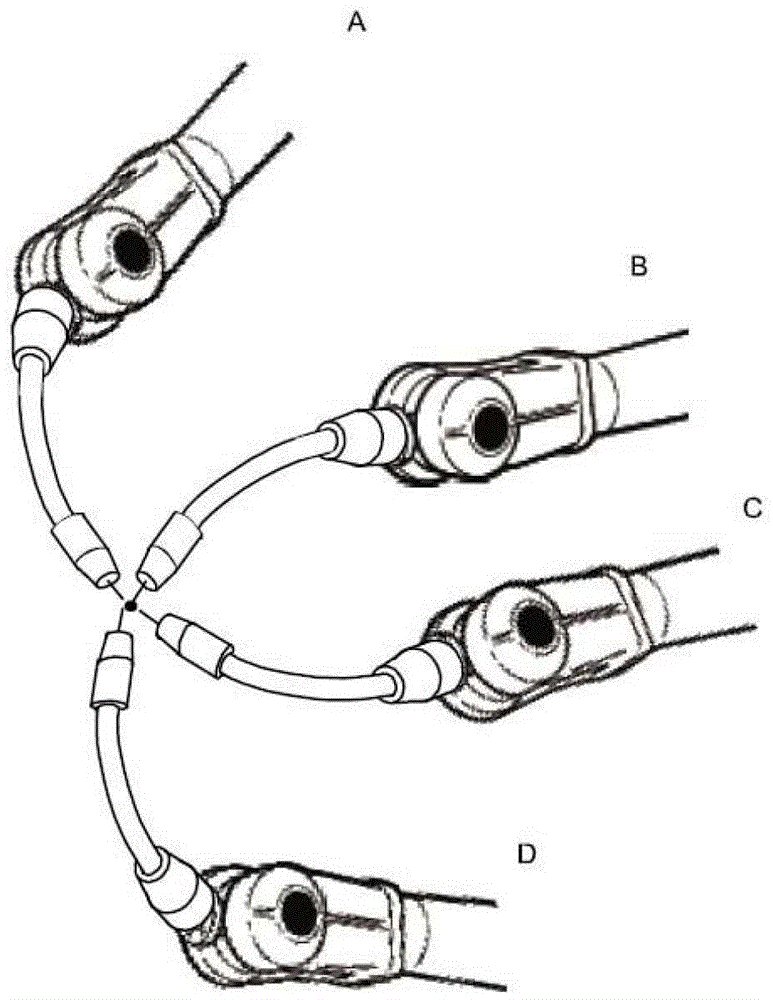
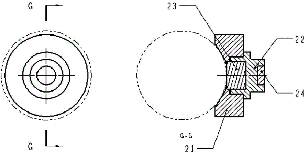
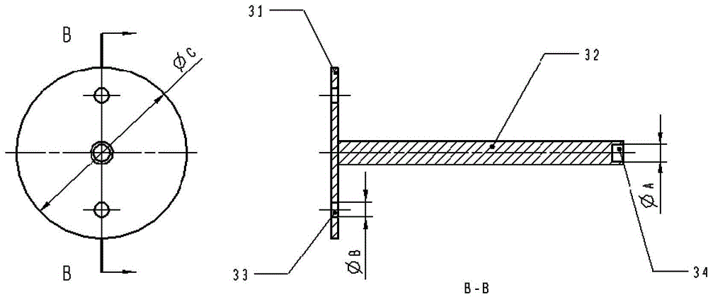
[0149] The non-contact high-precision calibration method of the robot base coordinate system of the present invention adopts the calibration finger tooling installed with the measuring ball, and the calibration finger tooling includes a space point positioning device, a robot flange extension rod, and a circular fitting sleeve; Refers to the installation of the tooling on the robot flange or tool body; the center of the measuring ball (that is, the center point of the measuring ball as the calibration point) is measured by the laser measuring instrument; the laser measuring instrument has a coordinate system of the laser measuring instrument, and the laser measuring instrument The measured data is processed through the algorithm of coordinate transformation, and the relationship between the coordinate system of the laser measuring instrument and the base coordinate system of the robot is established, so as to perform non-contact high-precision calibration of the base coordinate ...


PUM


Abstract

The invention discloses a non-contact high-precision calibration method for a robot base coordinate system, comprising the following steps: step 1, installing a calibration finger tool; step 2, taking points for calibration; and step 3, obtaining the robot's The calibration matrix of the base coordinate system. With the help of the advantages of high precision and non-contact measurement of the laser measuring instrument, the invention can realize the non-contact high precision of the robot base coordinate system through the position encoder of the robot's internal joints and the calibration finger tooling set, and the algorithm of coordinate transformation. The calibration of the robot and the non-contact high-precision calibration method of the workpiece coordinate system of a single robot and the non-contact high-precision calibration method of the tool coordinate system of a single robot can realize the non-contact high-precision calibration of the entire robot system calibration. The invention also discloses a non-contact high-precision calibration method for poses among multiple robots.

Description

technical field [0001] The invention relates to a calibration method of an industrial robot, in particular to a non-contact high-precision calibration method of a robot base coordinate system. The invention also relates to a non-contact high-precision calibration method for poses among multiple robots. Background technique [0002] The flexible processing and production unit based on industrial robots has become the main development direction of the manufacturing industry. Among them, the accurate control of the robot pose, the parametric programming of the robot, the high-precision coordination work of the robot group, the transformation of the robot pose, and the control of the robot system The needs of relocation, robot multi-station program sharing, robot trajectory planning, etc. are gradually becoming the focus of attention. All of the above aspects require the establishment of accurate models of the actual robot and its working environment, as well as other equipment...

Claims


Application Information

Patent Timeline
Patent Type & Authority Patents(China)
IPC IPC(8): G01B11/00
Inventor 朱笑奔汪航吴旭
Owner SHANGHAI MITSUBISHI ELEVATOR CO LTD
Why Eureka
Try Eureka