Non-contact high-precision calibration method and application of workpiece coordinate system of robot

A calibration method, non-contact technology, applied in the direction of instruments, optical devices, measuring devices, etc., can solve the problems of cumbersome operation, time-consuming, uncontrollable, etc.

Active Publication Date: 2014-11-26
SHANGHAI MITSUBISHI ELEVATOR CO LTD
View PDF5 Cites 11 Cited by
  • Summary
  • Abstract
  • Description
  • Claims
  • Application Information

AI Technical Summary

Problems solved by technology

like figure 1 Shown is the TCP (Tool Coordinate Point, Tool Coordinate System) calibration method of the robot. The operation of this calibration method is relatively cumbersome, and there are certain requirements for the space point. When the robot needs to keep the position of the space point unchanged, different The attitude is completed by several points; moreover, the calibration accuracy varies from operator to operator, and there are certain uncontrollable factors, which makes the value obtained after calibration have a large error, usually at the millimeter level, and takes a lot of time
The disadvantages of this calibration method cannot meet the requirements of modern production for higher precision of robots, higher efficiency of calibration operations, and higher calibration accuracy
[0005] Chinese patent 201010545419.7 discloses a robot tool coordinate system automatic calibration device and method based on laser tracking measurement, but it only calibrates the robot tool coordinate system, not the entire robot system, which causes even if the accuracy of the tool coordinate system reaches To a certain extent, but because the accuracy of other coordinate systems cannot match, it will also affect the accurate control of the robot's pose, the parametric programming of the robot, the high-precision coordination of the robot group, the transformation of the robot's pose, and the relocation of the robot system. Applications in robot multi-station program sharing, robot trajectory planning, etc.
In addition, the number of points taken during calibration is relatively large, and the operation is relatively cumbersome.
Most importantly, the calibration of the tool coordinate system is carried out for the tools designed by the author himself. In actual use, the tools at the front end of the robot are various according to different applications, so their practicability is not very high.

Method used


Image

  • Non-contact high-precision calibration method and application of workpiece coordinate system of robot
  • Non-contact high-precision calibration method and application of workpiece coordinate system of robot
  • Non-contact high-precision calibration method and application of workpiece coordinate system of robot

Examples


example

[0449] Example: complex robotic system process and method for recovery relocation.

[0450] system introduction:

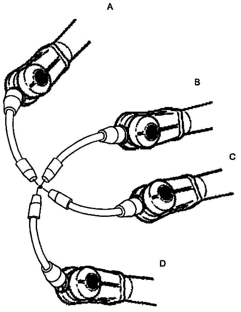
[0451] Such as Figure 8 As shown, the system has 4 robots: R1, R2, R3, R4. R1 has a cooperative relationship with R2 and R3. R4 has a cooperative relationship with R2, and has no cooperative relationship with R3, and R4 operates on the workpiece coordinate system on R3. R1 corresponds to the workpiece coordinate system R w1 , R2 corresponds to the workpiece coordinate system R w1 , R w2 , R3, R4 have no corresponding workpiece coordinate system.

[0452] The system consists of the following elements: e 1 = rob 1 , e 2 = rob 2 , e 3 = rob 3 , e 4 = rob 4 , e 5 = wobj 1 (R w1 for rob 1 ), e 6 = wobj 2 (R w1 for rob 2 ), e 7 = wobj 3 (R w2 for rob 2 ), e 8 = wobj 4 (wobj 4 ∈ rob 3 for rob 4 ), and e before relocation 1 = rob 1 , e 2 = rob 2 , e 3 = rob 3 , e 4 = rob 4 None of the base markings have been modified, so rob 1 ...


PUM


Abstract

The invention discloses a non-contact high-precision calibration method of a workpiece coordinate system of a single robot, comprising: first, calibrating a fundamental coordinate system of a robot; second, calibrating a workpiece coordinate system of the robot. The method provided by the invention, the non-contact high-precision calibration method of the fundamental coordinate system of the robot, and the non-contact high-precision calibration method of a tool coordinate system of the single robot employ a unified non-contact high-precision way, so that the precision of the whole system reaches a height that the calibration method in the prior art cannot touch. The calibration employed by the invention is that a tool sleeve can calibrate the workpiece coordinate system of the robot on an inclined surface. The calibration is that the tool sleeve can ensure repeatability of each operation, so as to furthest reduce errors generated by man-made calibration. The invention also discloses a method of making a robot system adapt a method of the change of the robot and the environment pose.

Description

technical field [0001] The invention relates to a calibration method for an industrial robot, in particular to a non-contact high-precision calibration method for a workpiece coordinate system of a single robot. The invention also relates to a method for enabling a robot system to adapt to changes in the pose of its robot and objects in the environment. Background technique [0002] The flexible processing and production unit based on industrial robots has become the main development direction of the manufacturing industry. Among them, the accurate control of the robot pose, the parametric programming of the robot, the high-precision coordination work of the robot group, the transformation of the robot pose, and the control of the robot system The needs of relocation, robot multi-station program sharing, robot trajectory planning, etc. are gradually becoming the focus of attention. All of the above aspects require the establishment of accurate models of the actual robot and...

Claims


Application Information

Patent Timeline
Patent Type & Authority Applications(China)
IPC IPC(8): G01B11/00
Inventor 朱笑奔汪航吴旭
Owner SHANGHAI MITSUBISHI ELEVATOR CO LTD
Why Eureka
Try Eureka