Grinding device for preparing near-field optical probes and method therefor

A technology of near-field optics and grinding devices, applied in chemical instruments and methods, grinding/polishing safety devices, cleaning methods using liquids, etc., can solve injuries, experimental parameters cannot be accurately controlled, and repeatability is not easy to guarantee, etc. problems, to achieve the effect of safe production process, easy and precise control of adjustment parameters, and flexible production methods

Inactive Publication Date: 2009-12-16
BEIHANG UNIV
View PDF4 Cites 23 Cited by
  • Summary
  • Abstract
  • Description
  • Claims
  • Application Information

AI Technical Summary

Problems solved by technology

However, because it is still a chemical method, there are still many experimental parameters that cannot be accurately controlled, such as the concentration of the corrosion solution, corrosion temperature and time, etc. It is reported that only changing the parameters of the coating solution will change the cone angle of the probe by 30 degrees as much
The dynamic erosion method can further modify the shape of the probe to form a fiber probe with a large cone angle (up to about 50 degrees) or multiple cone angles, but the repeatability in actual operation is not easy to guarantee
In addition, as the main component of the corrosive liquid, hydrogen fluoride is a volatile and highly toxic substance, and if the protective measures are not proper, it will cause great harm to the body of the experimenter.

Method used


Image

  • Grinding device for preparing near-field optical probes and method therefor
  • Grinding device for preparing near-field optical probes and method therefor
  • Grinding device for preparing near-field optical probes and method therefor

Examples


Embodiment Construction

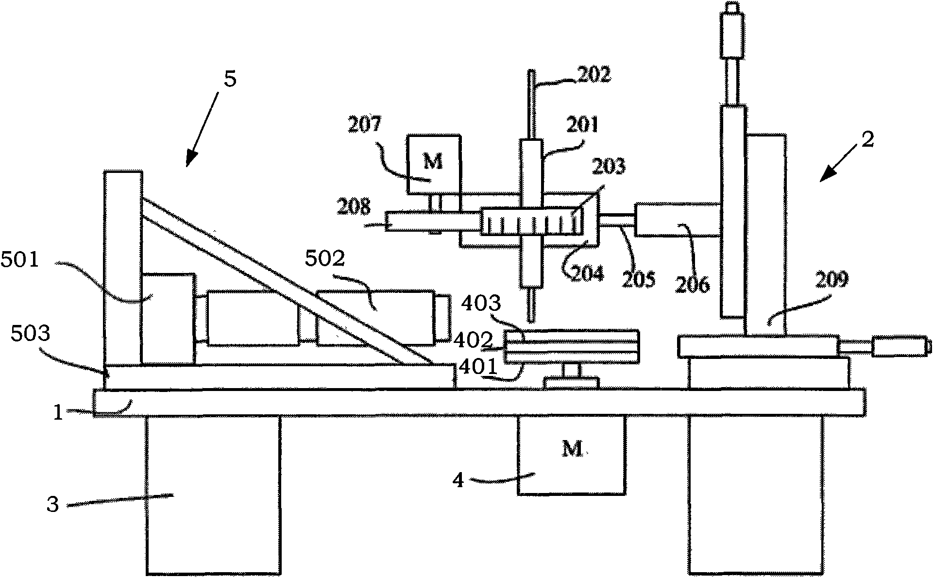
[0036] refer to figure 1 , the grinding device for preparing near-field optical probes provided by the present invention mainly includes a vibration-damping rubber 3 , a support base 1 , a three-phase brushless motor 4 , an adjustment frame 2 and an optical microscope 5 .

[0037] The support base plate 1 is horizontally arranged on the shock-absorbing rubber 3, a three-phase brushless motor 4 is fixed in the middle of the support base plate 1, and the two ends of the support base plate 1 are respectively provided with an adjustment frame 2 and an optical microscope 5. The adjustment The frame 2 is used to fix the optical fiber, and the optical microscope 5 is used to observe or monitor the grinding process of the optical fiber. Such as figure 1 As shown, a 5-inch circular aluminum plate is fixed on the main shaft of the three-phase brushless motor 4 as a rotating disc 401, and the rotating disc 401 is located above the middle of the support base plate 1, and a 5-inch grindin...


PUM


Abstract

The invention discloses a device for preparing near-field optical probes and a method therefor. The device comprises damping rubber, a support soleplate, a three-phase brushless motor, an adjusting bracket and an optical microscope, wherein the support soleplate is horizontally arranged on the damping rubber; and the three-phase brushless motor, the adjusting bracket and the optical microscope are fixed on the support soleplate. The method comprises the following steps: firstly, fixing a silica fiber on the adjusting bracket and above an abrasive substance in a set angle; and when the abrasive substance is rotated, making the fiber approach the abrasive substance and generate friction, rotating the fiber in different angles along the axial direction of the fiber, repeatedly approaching and rubbing a grinding sheet, and preparing the near-field optical probes with different shapes such as triangular pyramid, rectangular pyramid, circular cone and the like by grinding. The method overcomes the limitation of preparing the taper angle of a fiber optic probe, can directly set a grinding taper angle, and has flexible manufacturing mode, safe and environment-friendly manufacturing process, short preparation time, accurate control of parameters, good repeatability; and the whole device has simple and convenient operation and low preparation cost.

Description

technical field [0001] The invention relates to the preparation of optical fiber probes, in particular to a grinding device and method for preparing near-field optical probes, and belongs to the fields of nano-optics, near-field optics, scanning probe microscopy and the like. Background technique [0002] Near-field optical microscopy (abbreviated: SNOM or NSOM) is a new microscopic imaging technology that has emerged in the optical field since the 1980s. SNOM not only inherits the advantages of traditional optical microscopy, but also breaks through the constraints of diffraction effects, extending the resolution to below 100 nanometers. Using SNOM, people can not only obtain the microscopic topography of the material surface, but also obtain optical information. Today, SNOM has penetrated into various fields such as physics, chemistry, materials and biology. [0003] One of the cores of SNOM technology is the preparation technology of optical probes. Currently, most of ...

Claims


Application Information

Patent Timeline
Patent Type & Authority Applications(China)
IPC IPC(8): B24B19/16B24B49/12B24B55/00B08B3/12G12B21/06G01Q60/22
Inventor 蔡微商广义魏恩浩徐平姚骏恩
Owner BEIHANG UNIV
Why Eureka
Try Eureka