A method for manufacturing a heat-exchanger and a system for performing the method

A heat exchanger and equipment technology, applied in the field of manufacturing heat exchangers, can solve problems such as time-consuming, troublesome, unstable pipeline skeleton structure, etc., and achieve the effect of improving cost economy, high efficiency, and excellent thermal contact

Inactive Publication Date: 2007-11-21
SUNSTRIP
View PDF0 Cites 4 Cited by
  • Summary
  • Abstract
  • Description
  • Claims
  • Application Information

AI Technical Summary

Problems solved by technology

Due to the instability of the pipe skeleton structure, the work of correctly positioning the pipe skeleton structure on the homogeneous absorbing plate is usually very troublesome and time-consuming
This instability, combined with the residual stresses in the skeleton structure of the tubes, also makes it practically impossible to achieve close to one hundred percent contact between the tubes and the homogeneous absorber plates, which is certainly true for heat exchangers manufactured according to this known method. negatively affects the heat transfer capability of the

Method used


Image

  • A method for manufacturing a heat-exchanger and a system for performing the method
  • A method for manufacturing a heat-exchanger and a system for performing the method
  • A method for manufacturing a heat-exchanger and a system for performing the method

Examples


Embodiment Construction

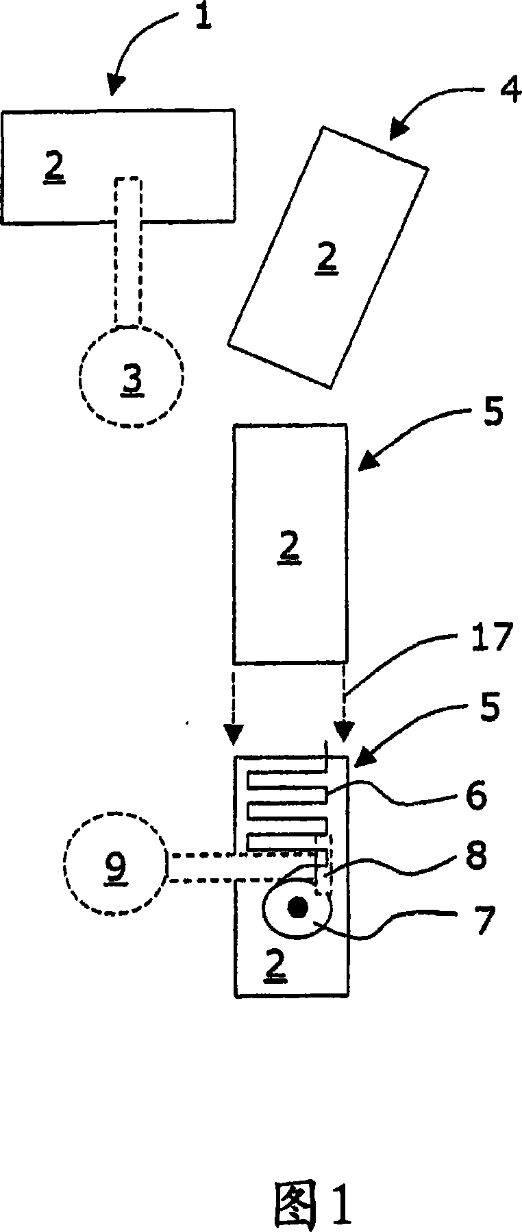
[0016] Figure 1 shows a schematic diagram of a system for manufacturing a heat exchanger according to the method of the present invention. The system comprises a reservoir 1 of sheet metal 2 of predetermined size. A handling system 3 , for example a preprogrammed automatic handling system, is used for handling the sheet metal 2 . However, it is obvious that any suitable handling system can also be used, including manual handling of the sheet metal 2 .

[0017] The handling system 3 is arranged to grab a piece of metal sheet 2 from the reservoir 1 and transfer it to the alignment unit 4 where it will be released and positioned in a predetermined well-defined position. As soon as the metal sheet 2 is in a predetermined defined position, the handling system 3 will grip the metal sheet 2 again and transfer it to the working platform 5 . Thanks to said alignment step, precise positioning on the working platform 5 is greatly facilitated. Thereafter the sheet metal 2 is secured in...


PUM


Abstract

The present patent application relates to a method for manufacturing a heat-exchanger and in particular a heat-exchanger suitable for energy transfer between a plate and a fluid circuit. A sheet metal plate (2) and a predetermined length of continuous metal tubing (6) is prepared. The length of metal tubing (6) is successively applied to the sheet metal plate (2), the successive application including: bringing the metal tubing (6) into close contact with the sheet metal plate (2); and affixing the metal tubing (6) to the sheet metal plate (2), preferably using laser welding.

Description

technical field [0001] According to the preamble of claim 1 , the present patent application relates to a method of manufacturing a heat exchanger, in particular a method of manufacturing a heat exchanger suitable for transferring energy between plates and fluid circuits. Background technique [0002] As home heating costs increase, there is a growing need for alternative environmentally friendly alternatives. One such alternative is to utilize energy readily available in the form of solar energy. In order to use the energy provided by the sun, solar collectors are generally used. These solar collectors may be based, for example, on the principle that the sun impinges on a dedicated surface to be absorbed by and heats the surface, and then transfers the heat from the surface to a fluid medium which facilitates the transfer of the heat to the desired Location. Accordingly, there is an increased demand for heat exchangers, especially heat exchangers suitable for absorbing e...

Claims


Application Information

Patent Timeline
Patent Type & Authority Applications(China)
IPC IPC(8): B21D53/08F24J2/26B23K26/24B23PF24S10/75F28F1/22
CPCF28F1/22B23K2203/12Y02E10/44B23K26/243B23K2201/14Y10T29/49364F28F2275/067B23K2203/10F24J2/268B21D53/08B23K26/242B21D11/07F24S10/755B23K2101/14B23K2103/10B23K2103/12F24S10/753B23P15/26
Inventor G·胡尔特马克
Owner SUNSTRIP
Why Eureka
Try Eureka