
Device and method for testing automotive active safety systems on bench
An active safety, bench testing technology, applied in the direction of measuring devices, vehicle testing, machine/structural component testing, etc., can solve the problems of large test preparation workload, poor repeatability, high test cost, and reduce the number of tests. Workload, easy to locate and reproduce, ensure reproducible results
- Summary
- Abstract
- Description
- Claims
- Application Information
AI Technical Summary
Problems solved by technology
Method used
Image

Examples
Embodiment Construction
[0032] The present invention will be further described below in conjunction with the accompanying drawings:
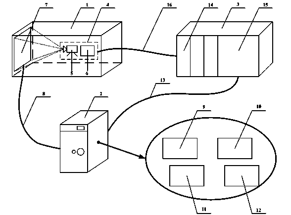
[0033] like figure 1 The bench test device for the automotive active safety system includes a camera obscura 1, a system to be tested 4, a display 7, a video cable 8, a host computer 2, a network cable 13, a lower computer 3 and a CAN bus 16. The lower computer 3 includes a real-time controller 15 and a CAN card 14 ; the system to be tested 4 includes a camera 5 and a controller 6 . The system to be tested 4 and the display 7 are installed inside the dark box 1, the display 7 is connected to the upper computer 2 through the video cable 8, the upper computer 2 is connected to the lower computer 3 through the network cable 13, and the lower computer 3 is connected to the standby computer through the CAN card 14 and the CAN bus 16. The controller 6 of the system under test 4 is connected, the camera 5 of the system to be tested 4 is aligned with the display 7, and the co...
PUM
 Abstract
Description
Claims
Application Information