An Equivalence Method of Power Grid Based on Phase Angle Difference of Tie Lines

A power grid equivalent and tie line technology, applied in the field of value, can solve the problem that the network equivalent simplification cannot be used, and achieve the effects of convenient related analysis and calculation, reduction of power grid scale, and good equivalent accuracy

Active Publication Date: 2016-04-20
CHINA SOUTHERN POWER GRID COMPANY +1
View PDF2 Cites 0 Cited by
  • Summary
  • Abstract
  • Description
  • Claims
  • Application Information

AI Technical Summary

Problems solved by technology

In the case that the grid power flow calculation does not converge, it will not be possible to use these static equivalent methods to perform equivalent simplification of the network

Method used


Image

  • An Equivalence Method of Power Grid Based on Phase Angle Difference of Tie Lines
  • An Equivalence Method of Power Grid Based on Phase Angle Difference of Tie Lines
  • An Equivalence Method of Power Grid Based on Phase Angle Difference of Tie Lines

Examples


Embodiment 1

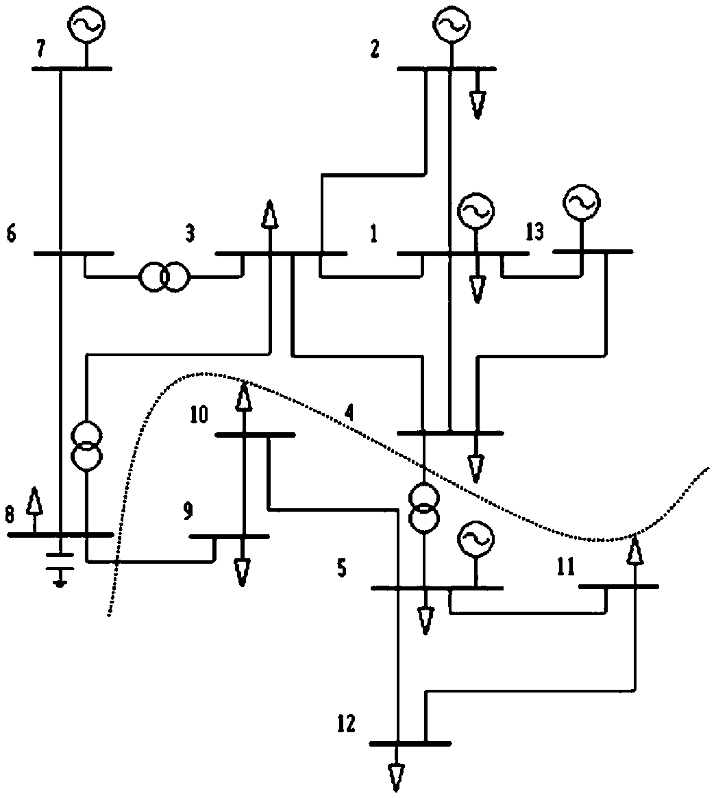
[0036] Such as figure 1 As shown, the grid equivalent method based on the tie line phase angle difference, the method includes the following steps:

[0037] a) Divide the test grid into two sub-grids. Subgrid A is composed of nodes 1, 2, 3, 4, 6, 7, 8, and 13, of which 4 and 8 are boundary nodes; subnet B is composed of nodes 5, 9, 10, 11, and 12, of which 5 and 9 is a boundary node; branch 4-5 and branch 8-9 are connection lines between subsystems;

[0038] b) Assuming that the voltage amplitude of all nodes in the power grid is 1, the voltage phase angle θ of each node is obtained by using the DC power flow method i (i=1,2,...13);

[0039] c) According to the obtained DC power flow solution, calculate the line power on branch 4-5 and the line power on branch 8-9 Will As the equivalent injection power, connect to node 4 and node 8 respectively.

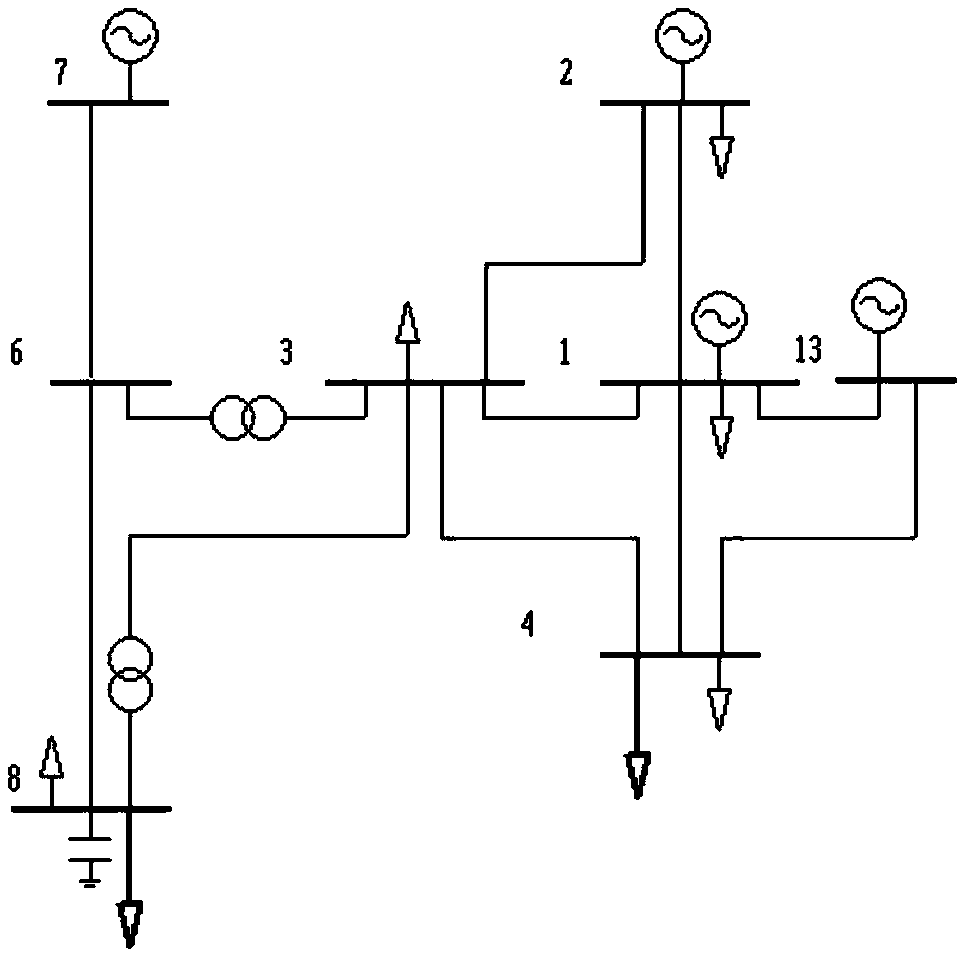
[0040] d) Obtain the grid equivalent network including only the equivalent injected power of sub-grid A and sub-grid B, suc...

Embodiment 2

[0047] On the basis of Example 1, the system load level is gradually increased from 1.0 times to 3.0 times, the power flow calculation is performed on the power grid after the equivalent value, and the approximate power flow result at this time is compared with the accurate power flow result before the equivalent value, and the table is obtained 2.

[0048] It can be seen from the results in the table that with the increase of the load level, the voltage amplitude and phase angle errors of all nodes are within 4%, which shows that the proposed equivalent model and method have good equivalence under different load levels. value precision.

[0049] Table 2 Comparison of power flow results of each node in sub-grid A under different load levels

[0050]

[0051]

[0052] The above calculation and analysis results show that the proposed equivalence model and calculation method can approximate the local power grid when the exact power flow solution of the power grid is unknow...


PUM


Abstract

The invention discloses a grid equivalent method based on phase angle difference of call lines. The grid equivalent method particularly comprises the steps of dividing a grid into a plurality of sub-grids, obtaining approximate load flow solvability of the grid by means of a direct-current load flow method, calculating line power of the call lines among the sub-grids on the basis of the approximate load flow solvability, and equalizing the line power onto boundary nodes of a network needing retaining in a mode of power injection. By means of the direct-current load flow method, the approximate load flow solvability of the grid can be obtained under most of the conditions, the equivalent scheme does not depend on an accurate load flow result of the grid, and therefore, approximate static equivalence can be achieved under the conditions that load flow calculation of the grid is not convergent. In addition, an established equivalent model is good in equivalent accuracy.

Description

technical field [0001] The invention belongs to the field of power system analysis, and more specifically relates to a power grid equivalent method based on tie line phase angle difference. Background technique [0002] With the rapid development of my country's social economy, the scale of the power grid continues to expand, the structure becomes more and more complex, the load level continues to increase, and the operation mode becomes more and more complex and changeable. Inconvenience in planning and operation. [0003] There are usually two reasons for this non-convergence of power flow calculation: one is that part of the calculation data in the complex power grid is given incorrectly, causing the power flow to have no solution, which is manifested as non-convergence in calculation; the other is that the scale of the power grid has expanded Finally, the commonly used Newton-Raphson method (Wang Xifan et al., Modern Power System Analysis. Beijing: Science Press, 2003. p...

Claims


Application Information

Patent Timeline
Patent Type & Authority Patents(China)
IPC IPC(8): H02J3/00
Inventor 陈金富李智欢苏寅生孙鑫黄河徐光虎文汀姚海成
Owner CHINA SOUTHERN POWER GRID COMPANY
Why Eureka
Try Eureka