Clamp type manual rapid pipe connecting device

A connecting device and a clamp-type technology, which are applied in the field of clamp-type manual quick pipeline connection devices, can solve the problems of low docking efficiency, heavy weight, labor and time-consuming operation, etc., and achieve fast and reliable docking, strong connection reliability, and operation. Convenient and fast effects

Active Publication Date: 2014-12-03
湖北三江航天红林探控有限公司
View PDF7 Cites 18 Cited by
  • Summary
  • Abstract
  • Description
  • Claims
  • Application Information

AI Technical Summary

Problems solved by technology

In the hydraulic docking method in the prior art, the claw is driven by the hydraulic cylinder through the connecting rod system, or the claw is directly driven by the guide mechanism, or the hydraulic motor drives the screw nut system through the gearbox to drive the claw to realize the connection between the two flanges. Although this type of connection is automated, it must be equipped with an electro-hydraulic control system, and 1 to 5 (mostly 3 to 5) hydraulic cylinders or Hydraulic motors, with a relatively complex structure, are more expensive, heavier, less reliable and inconvenient to maintain
[0005] In the manual docking method in the prior art, the operator mainly uses a special tool such as a wrench to tighten the wedge on the flange or tighten the lock nut and the connecting claw to complete the connection between the two flanges; this method The same as the hydraulic docking method, it is necessary to configure 3 to 5 standard wedges or connecting claws (jaws) according to the size of the connecting flange. In addition, special tools are required, and the operation is relatively labor-intensive and time-consuming, and the docking efficiency is low.

Method used


Image

  • Clamp type manual rapid pipe connecting device
  • Clamp type manual rapid pipe connecting device
  • Clamp type manual rapid pipe connecting device

Examples


Embodiment Construction

[0031] Below in conjunction with accompanying drawing and specific embodiment the present invention is described in further detail:

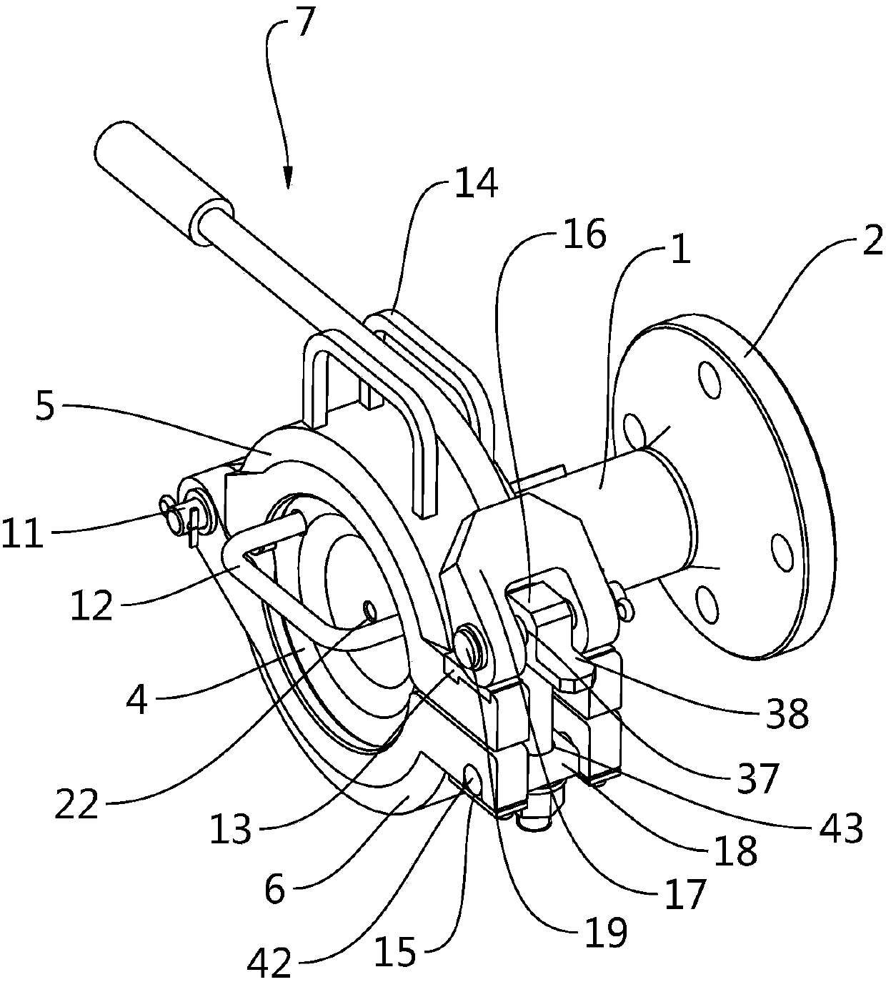
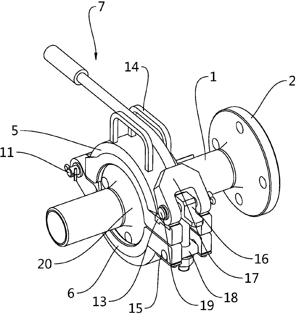
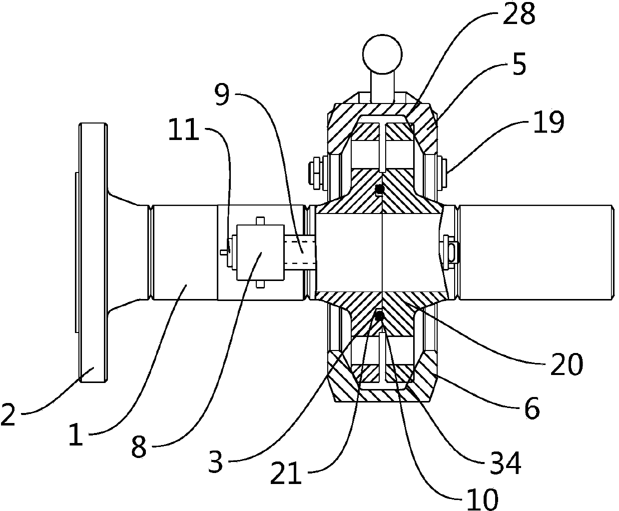
[0032] Such as Figures 1 to 7 As shown, the clamp type manual quick pipeline connection device designed in the present invention includes a medium pipeline 1, and one end of the medium pipeline 1 is provided with a connecting flange 2 that can be connected with the filling end equipment, and the medium pipeline 1 The other end is provided with a butt flange 3 that can be connected with the injection flange 20 of the equipment at the injection end, and it also includes an upper semicircle clamp 5 and a lower semicircle clamp 6 that cooperate with each other, a clamp compression mechanism 7, and a clamp Swivel bracket 8.

[0033] The clamp swivel support 8 is welded and fixed on the middle of the outer wall of the medium pipeline 1 , and the clamp swivel support 8 is provided with a clamp rotation pin 11 parallel to the axis of the medium pipeli...


PUM


Abstract

The invention discloses a clamp type manual rapid pipe connecting device. The clamp type manual rapid pipe connecting device comprises a medium guiding pipe, an upper semicircular clamp and a lower semicircular clamp, wherein a connecting flange and a counter flange are arranged at the two ends of the medium guiding pipe; the upper semicircular clamp is hinged to one end of the lower semicircular clamp; the other end is opened or closed through a clamping hold-down mechanism; the upper semicircular clamp and the lower semicircular clamp are hinged to the counter flange in the radial direction; the clamping hold-down mechanism is hinged to the lower semicircular clamp through a rotary shaft stop to operate the clamping hold-down mechanism to enable a lever cam to be pressed on the upper semicircular clamp, so that the counter flange can be butted with an infusing flange rapidly and reliably; a locking nut on an adjusting pulling rod is adjusted, so that the infusing flange with certain size deviation can be adapted. According to the invention, the clamp type manual rapid pipe connecting device is used for working conditions in which repeated assembling, disassembling and butting are needed, and has the advantages of simple structure, light weight, convenience and rapidity for operation, high connecting reliability, high working efficiency and the like.

Description

technical field [0001] The present invention relates to a pipeline connection device, in particular to a clamp-type manual fast pipeline connection device for fast connection of fluid delivery pipeline flanges between equipment at the filling end and equipment at the injection end; for example: storage tank process pipelines and automobile tankers The connection between the fluid loading and unloading arm and the tanker, the pipeline connection between the small marine fluid loading and unloading arm for transporting petrochemical products and the small ship. Background technique [0002] Fluid loading and unloading arms can be used for land transportation (including train transportation and automobile transportation) and water transportation (including ocean transportation and river transportation). The loading and unloading arms for ocean and river transportation are also called marine loading and unloading arms. The pipelines between the fluid handling arm and the tanker ...

Claims


Application Information

Patent Timeline
Patent Type & Authority Applications(China)
IPC IPC(8): B25B27/02
CPCB25B27/16
Inventor 万园朱方爽代文成
Owner 湖北三江航天红林探控有限公司
Why Eureka
Try Eureka