Cutting box of slot milling machine

A slot milling machine and box technology, which is applied in the direction of earth mover/shovel, construction, etc., can solve the problems of poor sealing performance, affecting the operation efficiency of underground diaphragm wall curtain wall construction quality, equipment failure of slot milling machine, etc.

Inactive Publication Date: 2013-06-12
上海工程机械厂有限公司
View PDF5 Cites 7 Cited by
  • Summary
  • Abstract
  • Description
  • Claims
  • Application Information

AI Technical Summary

Problems solved by technology

[0003] In the prior art, as the construction depth of the underground diaphragm wall increases, it is necessary to add the length of the cutting box of the TRD construction machine, and the cutting box is a box structure with lubricating oil pipelines, sensor pipelines, Compressed air pipes and liquid slurry pipes, when the cutting box of each unit is connected, generally use the cutting box end face sealing method to seal the above-mentioned lubricating oil pipeline, sensor pipeline, compressed air pipe and liquid slurry pipe, due to its poor sealing performance, As the milling depth of the underground diaphragm wall increases, the gradually increasing groundwater pressure will cause greater damage to the lubricating oil pipeline, sensor pipeline, compressed air pipeline and liquid slurry pipeline, resulting in leakage at the joints between the cutting boxes. Cause groundwater to invade the above-mentioned pipeline from the end face of the cutting box, cause equipment failure of the milling machine, affect the operation efficiency and the construction quality of the underground diaphragm wall and curtain wall

Method used


Image

  • Cutting box of slot milling machine
  • Cutting box of slot milling machine
  • Cutting box of slot milling machine

Examples


Embodiment 1

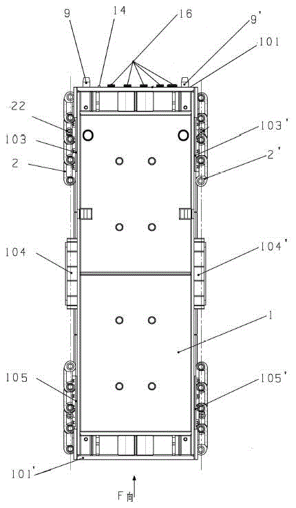
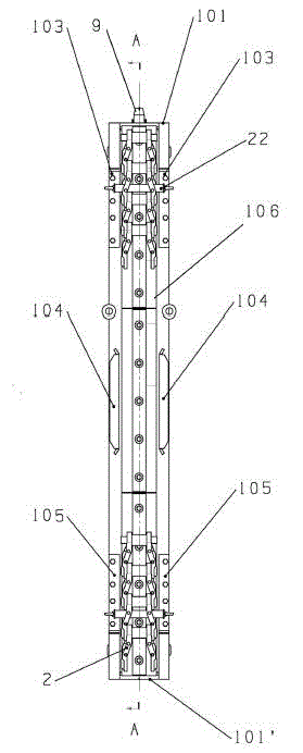
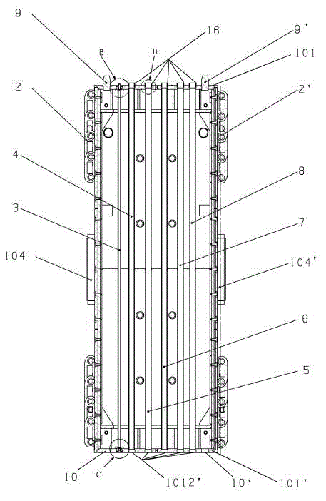
[0021] like Figure 1-Figure 8 As shown, a cutting box of a milling machine is composed of multiple unit cutting boxes, and each unit cutting box includes a box body 1, two chain groups 2, 2' located on the left and right sides of the box body, lubricating oil pipe 3, and conveying and transmission pipes , positioning pin 9, 9', positioning hole 10, 10', sealing seat 13, 13', quick joint 14, quick joint seat 15, sealing sleeve 16, the first O-ring 17 and the second O-ring 18 and the first Three O-shaped rings 19; it is characterized in that the box body 1 is a rectangular parallelepiped welded structure, and two upper fixing frames 103, 103' are arranged symmetrically from top to bottom on its left and right opposite sides. , guard plates 104, 104' and lower fixing frames 105, 105', which form guide grooves 106, 106' on the left and right sides of the box body 1; the two chain groups 2, 2' (each chain group includes rail joints , the pin shaft and the tool set on the rail joi...

Embodiment 2

[0025] The difference from Embodiment 1 is that the delivery and transmission pipeline includes a first air tube 4 , a first slurry tube 5 and a sensor cannula 8 .


PUM


Abstract

The invention provides a cutting box of a slot milling machine. The cutting box is formed by a plurality of unit cutting boxes, wherein each unit cutting box comprises a box body, two chain sets, a lubricating oil pipe, a conveying and transporting pipeline, a positioning pin, sealing bases, a rapid connector, a rapid connector base, a sealing sleeve and an O-shaped ring; the two chain sets are arranged on the left and right side faces of the box body; the lubricating oil pipe and the conveying and transporting pipeline are arranged in an inner cavity of the box body along a vertical direction of the box body in a manner of being parallel to each other; the lubricating oil pipe is provided with concave pits on the outer end faces of an upper cover plate and a lower cover plate; the sealing bases are screwed in the concave pits; the rapid connector and the rapid connector base are respectively screwed in the sealing bases; the conveying and transporting pipeline is provided with counter bores in the outer end faces of the upper cover plate and the lower cover plate; one half of the sealing sleeve is placed in the counter bore of the upper cover plate and the other half of the sealing sleeve protrudes and is in relative sealed match with the counter bore of the lower cover plate of the box body; and the positioning pin of the upper cover plate is complemented with a positioning hole in the lower cover plate. According to the cutting box of the slot milling machine disclosed by the invention, the butt joint accuracy of the cutting box is ensured so that the sealing performance of the lubricating oil pipe and the conveying and transporting pipeline is improved and the working stability of equipment is ensured.

Description

technical field [0001] The invention relates to a slot milling machine cutting box used for the cement reinforced underground continuous wall construction method, in particular to a cutting box which can be widely used for foundation engineering, underground foundation retaining wall, foundation pit wall support, embankment reinforcement and soft Soil foundation, etc. for improvement construction. Background technique [0002] At present, it is widely used in foundation engineering of high-rise buildings, excavation of underground roads and public ditches, shield shafts, retaining walls of underground foundations, water-stop walls, support of foundation pit walls, harbor seawalls, and reservoir dams. In foundation reinforcement and soft soil (liquid) foundation improvement construction, due to the continuous wall construction method (TRD construction method) of cement reinforcement soil, the construction machine height is low, the overall machine stability is good, and the w...

Claims


Application Information

Patent Timeline
Patent Type & Authority Applications(China)
IPC IPC(8): E02F5/02E02F5/06E02F5/14
Inventor 张鹏吴阎松段国平梁同舟
Owner 上海工程机械厂有限公司
Why Eureka
Try Eureka