Spring buffer type automatic argon blowing connector

A spring buffer and connector technology, which is applied in the direction of casting molten material container, electric charge composition/state, lighting and heating equipment, etc., can solve the problems of high risk of docking equipment, damage of argon blowing device, difficult operation, etc., and achieve reduction Equipment collision damage accidents, lower positioning accuracy requirements, and easy and convenient operation

Active Publication Date: 2017-06-13
WUHAN UNIV OF SCI & TECH
View PDF7 Cites 7 Cited by
  • Summary
  • Abstract
  • Description
  • Claims
  • Application Information

AI Technical Summary

Problems solved by technology

[0004] At present, in the external refining production process of domestic steel mills, the connection between the argon supply device on the ladle car and the argon connection device on the ladle is mainly achieved by manually connecting the pipes, which has the risk of injuring people due to molten steel turning over and splashing, and low efficiency ; Some enterprises adopt fixed docking plug devices, the plug part is installed on the ladle car, and the socket part is installed on the steel ladle. The docking needs to be realized by the accurate seating and positioning on the ladle car during the hoisting and lowering of the steel ladle. This kind of docking technology exists as follows Problems: 1. The crane driver lowers the ladle to the ladle car through eye observation and judgment in the traffic control room. To make the ladle sit on the fixed position on the ladle car accurately, the operation is difficult and the risk of damaging the docking equipment is great. ; 2. Manual adjustment and alignment takes a long time, resulting in delayed argon blowing operation time, large cooling of molten steel, and increased production costs; 3. The docking device on the ladle car and the ladle is fixed. Once the ladle falls off, it is easy to cause argon blowing at the bottom The device is damaged, affecting the refining production outside the furnace

Method used


Image

  • Spring buffer type automatic argon blowing connector
  • Spring buffer type automatic argon blowing connector

Examples


Embodiment Construction

[0019] A spring-buffered automatic argon blowing connector of the present invention will be described in detail below through specific embodiments in conjunction with the accompanying drawings.

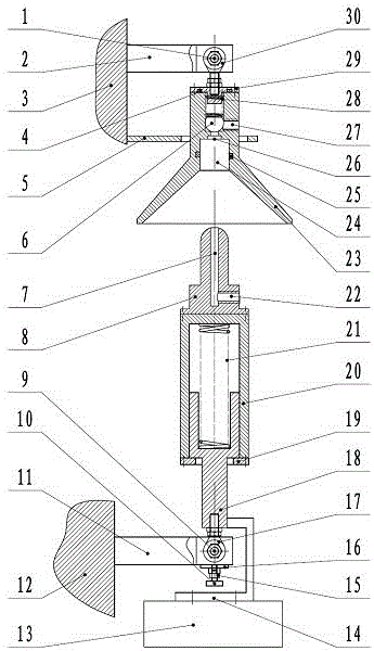
[0020] A spring-buffered automatic argon blowing connector of the present invention includes an argon sending mechanism, an argon receiving mechanism, an axis automatic calibration suspension mechanism, a deflection range limiting mechanism and other parts.

[0021] The docking buffer spring 21 is installed in the middle of the chamber formed by the docking buffer seat 18 and the docking buffer sleeve 20, which can slide relatively in the axial direction; The upper end of the guide head 8 of the argon delivery mechanism is spherical, the lower part is provided with a radial argon inlet port 22, and the middle is provided with an axial argon delivery channel 7. During operation, argon gas enters through the radial argon inlet interface 22 and passes through the argon delivery channel 7....


PUM


Abstract

The invention discloses a spring buffer type automatic argon blowing connector. The spring buffer type automatic argon blowing connector comprises an argon sending mechanism, an argon receiving mechanism, an automatic axis calibrating and hanging mechanism and a deflection range restricting mechanism. The spring buffer type automatic argon blowing connector has the advantages that due to design of an argon sending mechanism guiding head, a loudspeaker guiding opening and a dual-sealing structure composed of butt joint soft sealing and butt joint hard sealing, butt joint and coordination are smooth, and airtightness of a transportation channel is good; due to design of the automatic axis calibrating and hanging mechanism and the deflection range restricting mechanism, argon blowing connection can be implemented and completed in a larger deviation range, center positioning accuracy requirement when a steel ladle settles down is greatly reduced, and operation of a crane driver is much easier; and due to design of a buffer device, collision and damage accidents of equipment can be reduced, and reliability is high.

Description

technical field [0001] The invention relates to the field of pressure gas supply and control in industrial production such as modern steelmaking, furnace refining, etc., in particular to a spring buffer type automatic argon blowing connector. Background technique [0002] At present, with the development of science and technology and the improvement of steel quality requirements in industry and agriculture, modern steelmaking plants generally adopt out-of-furnace refining production processes to adjust and improve the content of trace elements in molten steel and improve the quality of billets. Refining outside the furnace has become an indispensable and important link in the modern steelmaking process. [0003] Refining outside the furnace is to add argon gas to the bottom of the ladle while adding alloy raw materials into the molten steel. The alloy components react quickly and mix evenly, so as to precisely adjust the content of trace elements and improve the quality o...

Claims


Application Information

Patent Timeline
Patent Type & Authority Applications(China)
IPC IPC(8): C21C7/072B22D11/117B22D41/58F27D99/00
CPCB22D11/117B22D41/58C21C7/072F27D99/0073F27M2001/02
Inventor 杨哲陈新元钟东阶刘琥铖詹瞩郑华生
Owner WUHAN UNIV OF SCI & TECH
Why Eureka
Try Eureka