Compound support leg disk mounting device for engineering vehicle

A technology for engineering vehicles and installation devices, applied in vehicle maintenance, lifting vehicle accessories, transportation and packaging, etc., can solve problems affecting vehicle transfer and off-road driving performance, affecting vehicle driving stability, and vehicle gap failure. Improve site adaptability and off-road driving performance, save labor time and work intensity, and increase the effect of minimum ground clearance

Inactive Publication Date: 2014-12-03
四川长江工程起重机有限责任公司
View PDF8 Cites 0 Cited by
  • Summary
  • Abstract
  • Description
  • Claims
  • Application Information

AI Technical Summary

Problems solved by technology

[0006] In order to increase the minimum distance from the ground, the passing angle, and the departure angle of the vehicle, the suspension of the engineering vehicle is often increased, thereby increasing the height of the vehicle's center of gravity, and the increase in the height of the center of gravity not only affects the driving stability of the vehicle, but also affects the engineering vehicle. The stability of the operation, the height of engineering vehicles is also limited by road regulations
[0007] In the prior art, although the commonly used push-pull foot plate can push the foot plate into the width range of the vehicle, the height direction cannot be adjusted, and the installation position of the foot plate is single, requiring frequent operation of the foot plate. When the state enters the driving state, for the special work site of the engineering vehicle, its lower minimum ground clearance, passing angle and departure angle may cause the gap failure of the vehicle, and also affect the transfer and off-road driving performance of the vehicle

Method used


Image

  • Compound support leg disk mounting device for engineering vehicle
  • Compound support leg disk mounting device for engineering vehicle
  • Compound support leg disk mounting device for engineering vehicle

Examples


Embodiment Construction

[0026] The present invention will be further described in detail below in conjunction with the drawings.

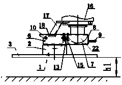
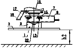
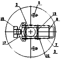
[0027] Such as Figure 1 to Figure 12 As shown, the composite foot plate installation device of the engineering vehicle includes a leg cylinder 16 and a foot plate 1. The foot plate 1 includes a welded and fixed bottom plate 3 and a ball socket 2. The top of the ball socket 2 is provided with a spherical shape In the groove, the bottom plate 3 is provided with two special-shaped pin holes 5, each of the special-shaped pin holes 5 includes two connected circular holes of different diameters; on the top of the ball socket 2 is fixedly connected a carriage 6, the carriage 6 includes two parallel and spaced apart The channel steel 7, the connecting plate 8 connecting the front end of the two channel steel 7, the handle 9 fixedly connected to the connecting plate 8, the notches of the two channel steel 7 are arranged oppositely, and the rear end of the lower leg plate of the two c...


PUM


Abstract

The invention discloses a compound support leg disk mounting device for an engineering vehicle. A support leg disk comprises a bottom plate and bulb recesses, the tops of the bulb recesses are fixedly connected with a sliding frame, the sliding frame comprises two parallel spaced channel steels and a connecting plate for connecting the two channel steels, notches of the two channel steels are opposite, the rear ends of lower leg plates of the two channel steels are connected with the bulb recesses on two sides of a spherical groove, waist plates of the two channel steels are provided with three groups of pin holes, pins are arranged in two groups of pin holes, a bolt is arranged at one end of each pin, a bracket is fixedly connected onto a support leg cylinder corresponding to the support leg disk and provided with a supporting plate, two suspension pin bosses are arranged in the rear of a vehicle chassis, and bolts are arranged at the outer ends of the two suspension pin bosses. The compound support leg disk mounting device has the advantages of simple structure, rapidness in adjustment and fine universality, the minimum ground distance, the passing angle and the departure angle of the engineering vehicle are increased, and the site adaptability and the cross-country running performance of the engineering vehicle are improved.

Description

Technical field [0001] The invention relates to a composite foot plate mounting device for engineering vehicles. Background technique [0002] In construction vehicles, such as cranes, aerial work vehicles, fire trucks, etc., in order to maintain the balance of the body, it is usually necessary to use support devices, such as using movable outriggers and other structures to support to maintain balance. At the bottom of the vertical cylinder of the movable outrigger, A foot plate is usually installed, and the movable leg is in contact with the ground through the foot plate. [0003] The foot plate is generally installed on the round ball head of the outrigger cylinder. In order to reduce the pressure exerted by the construction vehicle on the ground or backing plate, prevent the ground from sinking, and ensure the reliability and stability of the construction vehicle during operation, the size of the foot plate is usually relatively large . [0004] In order to improve the workin...

Claims


Application Information

Patent Timeline
Patent Type & Authority Applications(China)
IPC IPC(8): B60S9/10
Inventor 胡文才卓勋王大李西德彭建军罗庆彬
Owner 四川长江工程起重机有限责任公司
Why Eureka
Try Eureka