Super-clutch type multi-bridge driving mechanism
A technology of overrunning clutch and driving mechanism, which is applied in the direction of control devices, transportation and packaging, and vehicle components, and can solve problems such as the complex structure of the anti-skid differential chassis, the complex structure of the automobile chassis, and the increase in the cost of automobile manufacturing, and achieve the goal of increasing the minimum distance. Ground clearance, simple structure, reduced turning radius
- Summary
- Abstract
- Description
- Claims
- Application Information
AI Technical Summary
Problems solved by technology
Method used
Image
Examples
Embodiment 1
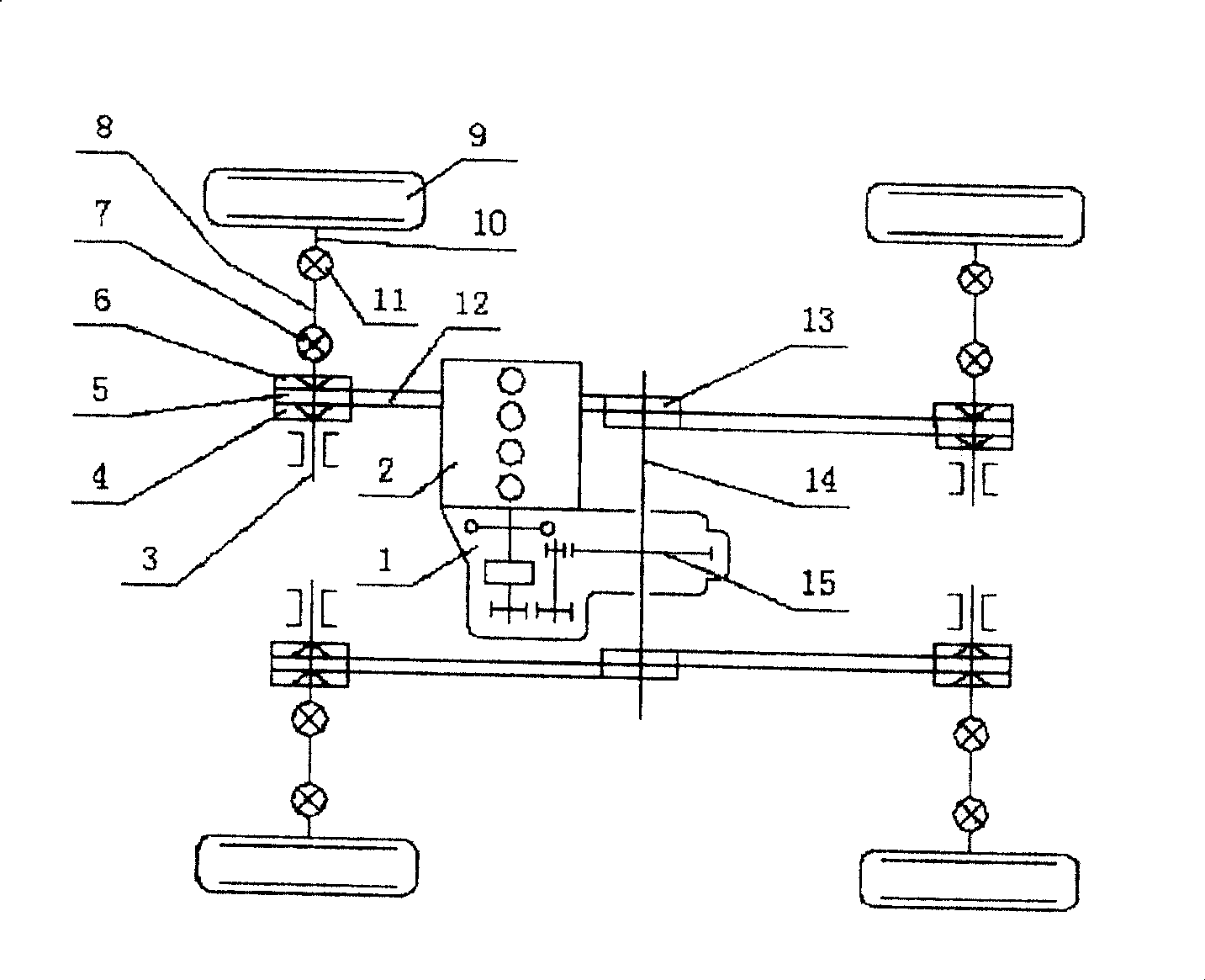
[0022] attached figure 1 As shown, the power from the engine 2 is transmitted to the drive shaft 14 through the driving gear 15, and then the power is transmitted through the first sprocket 13, the chain 12, the overrunning clutches 4, 6, and the universal joint 7 driven backward and forward. To drive the wheels 9, because the drive structure is symmetrical front and back and left and right, four wheel drives can be realized. When the car is running on a curve or due to different tire radii, the running speeds of the four wheels will be different. The overrunning clutches 4 and 6 driven backward and forward allow the wheels that rotate faster to Free overrunning rotation eliminates rolling interference between wheels and avoids unnecessary additional force between wheels.
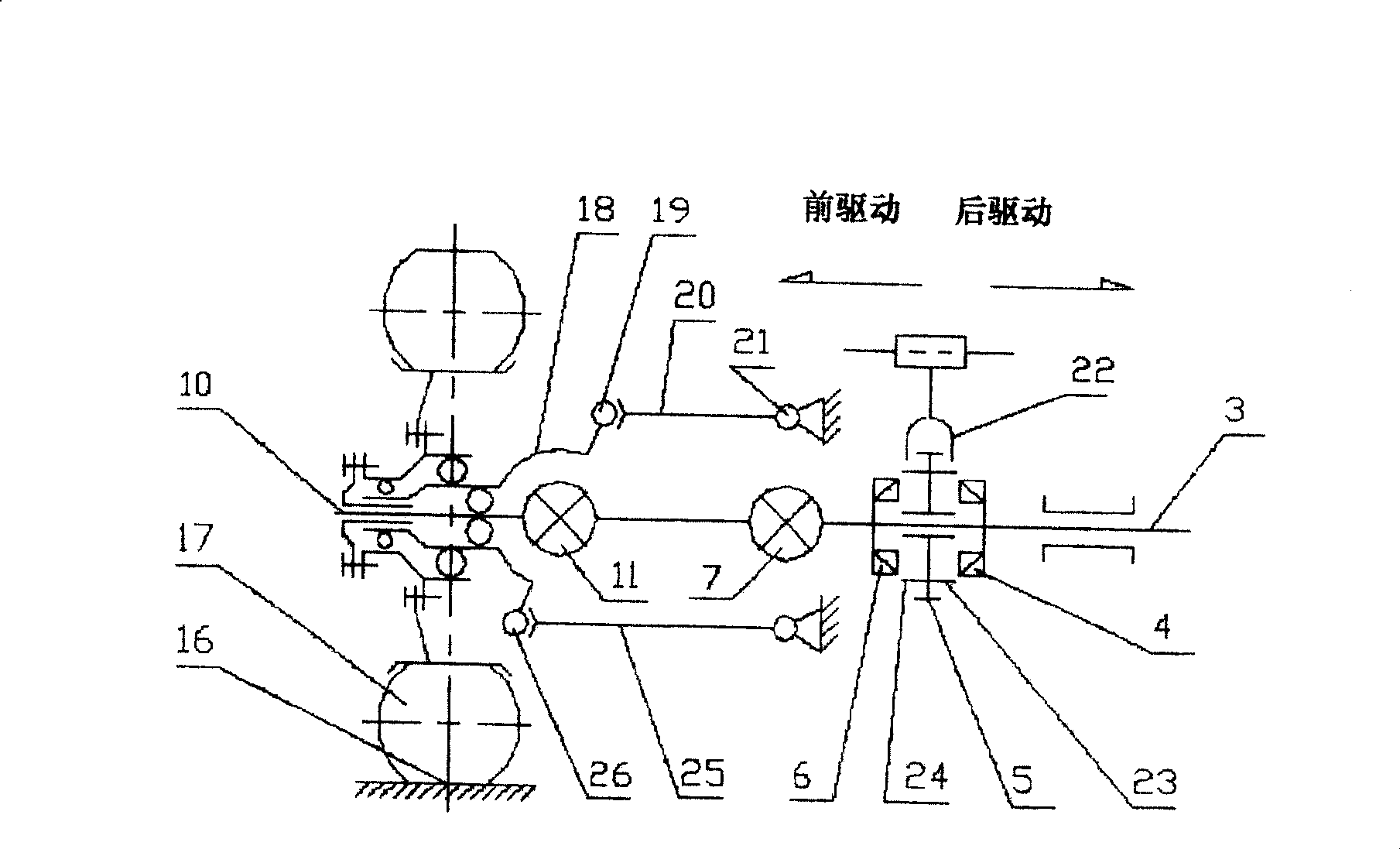
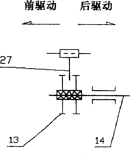
[0023] The structure of the semi-drive axle and the control method of the transmission direction are as attached figure 2 As shown, the power from the driving first sprocket 13 is transmitted to the seco...
Embodiment 2
[0026] Attached below Figure 4 Shown is further described to invention embodiment 2:
[0027] The difference between embodiment 2 and embodiment 1 is that: a drive axle and chain 12 are added to the 4WD mode to directly become the 6WD mode. The magnitude of the drive torque for the six wheels depends on the actual rotational speed of each wheel. Due to the overrunning action of the overrunning clutches 4 and 6 driven backwards and forwards, the short-time 6WD mode of the illustrated car can also be realized. The six wheels of the car will have different rotational speeds due to the different turning radii when driving on a curve. Even when driving in a straight line, the rotational speeds between the wheels will be slightly different due to the difference in tire radius. Under any conditions, the 6WD mode can automatically adjust the number of driving wheels within the range between one wheel drive and six wheel drive. The method is similar to that of whipping a slow ox. A...
Embodiment 3
[0029] Attached below Figure 5 and Figure 6 Shown further description to embodiment 3 of the present invention:
[0030] The difference between Embodiment 3 and Embodiment 1 is that: adding a drive axle to the 4WD mode directly becomes the 6WD mode. The feature of this embodiment is that the half drive axle is directly added to the shaft end of the drive shaft 14 . Structure and transmission direction control mode between its drive shaft 14 and the first sprocket 13 are as attached Figure 6As shown, a sliding splined connection is used. The left and right covers 35, 34 of the first sprocket wheel 13, connecting disc 32, spline type connecting sleeve 33 and sprocket wheel constitute a part. The splined connection sleeve 33 and the drive shaft 14 adopt a sliding spline connection to transmit power, and are supported on the shaft 14, while the outer drive shaft 29 and two clutches 30, 31 constitute a part, and are supported on the spline On the outer shaft diameter of the...
PUM
 Abstract
Description
Claims
Application Information
 - R&D
- Intellectual Property
- Life Sciences
- Materials
- Tech Scout
- Unparalleled Data Quality
- Higher Quality Content
- 60% Fewer Hallucinations
Browse by: Latest US Patents, China's latest patents, Technical Efficacy Thesaurus, Application Domain, Technology Topic, Popular Technical Reports.
© 2025 PatSnap. All rights reserved.Legal|Privacy policy|Modern Slavery Act Transparency Statement|Sitemap|About US| Contact US: help@patsnap.com


