Rotating mechanism for automatic piling up device

A technology of automatic stacking device and rotating mechanism, applied in the direction of hoisting device, etc., can solve the problems that the steering angle of the rotating structure cannot be adjusted, cannot meet the multi-angle rotation stacking, and the positioning accuracy cannot meet the requirements, so as to improve the scope of application and stability. , The effect of stacking neatly and reducing the failure rate

Inactive Publication Date: 2014-12-03
信阳雄狮装备科技股份有限公司
View PDF12 Cites 4 Cited by
  • Summary
  • Abstract
  • Description
  • Claims
  • Application Information

AI Technical Summary

Problems solved by technology

Due to the backlash of the sprocket, chain or rack and pinion, the positioning accuracy cannot meet the requirements after the grabbing rotates at a certain angle, and the impact of the oil cylinder or cylinder turning is too large, and the grabbing mechanism is prone to swing. The angle between adobes is prone to deviation, the adobes are not neatly stacked, the brick stack is unstable, and it is easy to collapse; and the steering angle of the existing rotating structure cannot be adjusted, which cannot meet the multi-angle rotation stacking

Method used


Image

  • Rotating mechanism for automatic piling up device

Examples


Embodiment Construction

[0011] The technical solutions of the present invention will be described in further detail below through specific implementation methods.

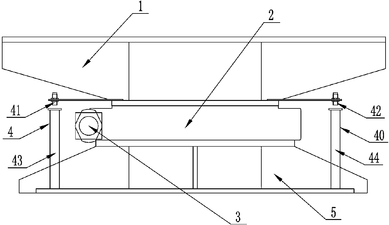
[0012] see figure 1 , the embodiment of the present invention provides a rotating mechanism of an automatic stacking device, the rotating mechanism is arranged at the lower end of the connecting frame 1 of the lifting mechanism. The rotary mechanism includes a rotary drive pair 2 , a motor reducer 3 and a hanger 5 . The slewing drive pair 2 is respectively connected with the connecting frame 1 and the hanger 5 . The motor reducer 3 is installed on the rotary drive pair 2 and drives the rotary drive pair 2 .

[0013] The rotary drive pair 2 is installed on the connecting frame 1 and the hanger 5 . The rotary drive pair 2 includes an inner ring of the rotary drive pair and an outer ring connected to the inner ring of the rotary drive pair. The inner ring of the rotary drive pair is fixedly installed on the connecting frame. The hanger ...


PUM


Abstract

The invention provides a rotating mechanism for an automatic piling up device. The rotating mechanism is arranged at the lower end of the lifting mechanism of the automatic piling up device. The rotating mechanism comprises a swing driving pair, an electric motor speed reducer, a connecting frame and a hanger, wherein the inner ring of the swing driving pair is fixed on the connecting frame; the outer ring of the swing driving pair is fixed on the hanger and comprises a turbine capable of enabling the outer ring of the swing driving pair to rotate; a worm matched with the turbine is mounted on the connecting frame; the electric motor speed reducer is mounted on the connecting frame; the turbine is driven to rotate by the electric motor speed reducer through the worm. According to the invention, the rotating mechanism has the characteristics of being stable in structure, multi-angle in rotation, accurate in rotating and positioning and low in failure rate.

Description

technical field [0001] The invention relates to an automatic brick stacking device, in particular to a rotating mechanism of the automatic stacking device. Background technique [0002] In the production of brick and tile building materials, the mud strips extruded by the brick extrusion machine are cut into pieces by the cutter, and the rows of bricks are arranged according to the required spacing through the marshalling conveying mechanism, and the marshaled bricks are grasped by the grabbing mechanism. Take it to the kiln car and stack it; according to the process requirements, two adjacent layers of adobes should be stacked at a certain angle to ensure that the stacked bricks are neat, and the upper and lower adobes are overlapped firmly, and it is not easy to collapse in the subsequent drying and roasting process. [0003] In the stacking devices used in China recently, the rotating mechanism adopts sprocket chain steering, rack and pinion steering, or oil cylinder and ...

Claims


Application Information

Patent Timeline
Patent Type & Authority Applications(China)
IPC IPC(8): B66F9/02
Inventor 郝忠良
Owner 信阳雄狮装备科技股份有限公司
Why Eureka
Try Eureka