Vibrating stone pushing device under rails

A technology for steel rails and vibration motors, which is applied to tracks, roads, ballast layers, etc., can solve problems such as low work efficiency, difficult cleaning, and sleeper damage, and achieve the effects of convenient operation, high mechanized operation rate, and easy program automatic control.

Inactive Publication Date: 2016-02-10
KUNMING UNIV
View PDF7 Cites 0 Cited by
  • Summary
  • Abstract
  • Description
  • Claims
  • Application Information

AI Technical Summary

Problems solved by technology

[0002] During the long-term use of railway sleepers, due to natural settlement and vibration, individual sleepers are damaged and need to be replaced in time. In the process of sleeper replacement, the ballast under the rail is more difficult to clean than the ballast between the sleepers. Using the existing machinery to clean up the ballast is time-consuming and inefficient, and the work cannot be completed within the effective train passage gap (commonly known as: skylight)

Method used


Image

  • Vibrating stone pushing device under rails
  • Vibrating stone pushing device under rails
  • Vibrating stone pushing device under rails

Examples


Embodiment Construction

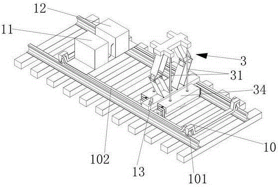
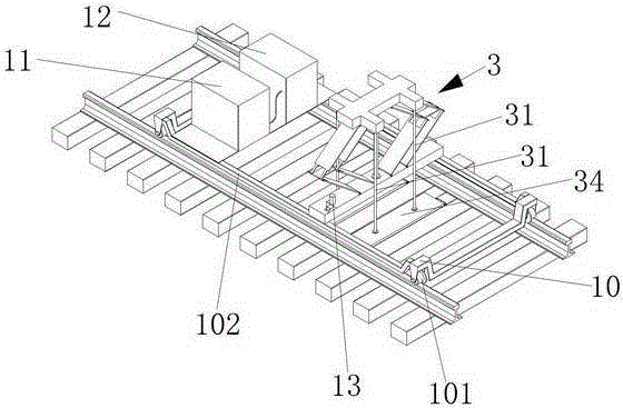
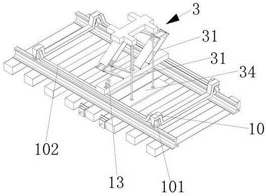
[0029] see Figure 1 to Figure 11 Shown, be the embodiment of the present invention, this embodiment is made up of vibrating rock pushing device 3, rail car 10, generator 11, hydraulic system box 12, camera assembly 13 and monitor, and rail car 10 is equipped with four casters 101 and two longitudinal beams 102, the vibrating stone pushing device 3, the generator 11 and the hydraulic system box 12 are arranged on the two longitudinal beams 102 of the rail car 10, the rail car 10 is pulled by an engineering vehicle, and the monitor 14 is located on the engineering vehicle In the cab, the generator 11 provides power for the oil pump and the vibrating motor, and the hydraulic system box 12 is provided with an oil tank, an oil pump, and various hydraulic pressure control valves.

[0030] The vibrating rock pushing device 3 is composed of a lifting mechanism 30, four suspenders 31 with flanges at both ends and two vibrating rock pushing assemblies 34. The lifting mechanism 30 is co...


PUM


Abstract

The invention discloses an under-rail vibrating ballast pushing device. The under-rail vibrating ballast pushing device is composed of vibrating ballast pushing devices, a railway car, a generator, a hydraulic system manifold, a camera assembly and a monitor. The railway car is provided with four trundles and two longitudinal beams; the vibrating ballast pushing devices, the generator and the hydraulic system manifold are arranged on the two longitudinal beams of the railway car; the railway car is pulled through an engineering car; the monitor is arranged inside the cab of the traction car; the generator powers an oil pump and a vibrating motor; the camera assembly is composed of a camera and a camera support, wherein the camera support is provided with an isosceles trapezoid reference plane coplanar with the axis of the camera, and a bottom plate; the inside of the hydraulic system case is provided with an oil tank, the oil pump and various hydraulic control pressure valves. The under-rail vibrating ballast pushing device can rapidly align the two vibrating ballast pushing assemblies to the space between the two side sleeper bodies of a sleeper to be replaced to push ballast under steel rails between the sleeper bodies rapidly, is applicable to ballast pushing of linear and curved rail sections, and can easily achieve programmed automatic control and operating convenience.

Description

technical field [0001] The invention relates to a railway maintenance machine, in particular to a vibrating rock-pushing device under rails. Background technique [0002] During the long-term use of railway sleepers, due to natural settlement and vibration, individual sleepers are damaged and need to be replaced in time. In the process of sleeper replacement, the ballast under the rail is more difficult to clean than the ballast between the sleepers. The use of existing machinery to clean up the ballast is time-consuming and inefficient, and the work cannot be completed within the effective train passage gap (commonly known as: skylight). Contents of the invention [0003] The object of the present invention is to provide a vibrating stone pushing device under the steel rail. [0004] The present invention is made up of vibrating rock pushing device, rail car, generator, hydraulic system box, camera assembly and monitor, rail car is equipped with four casters and two long...

Claims


Application Information

Patent Timeline
Patent Type & Authority Patents(China)
IPC IPC(8): E01B27/04
Inventor 刘景扬于向军
Owner KUNMING UNIV
Why Eureka
Try Eureka