Transmission parking pawl actuation assembly

A technology for actuating components and transmissions, applied to vehicle components, brake components, brakes, etc., can solve the problems of increasing complexity, weight cost and packaging size, and increasing the overall performance of the transmission

Active Publication Date: 2014-12-03
GM GLOBAL TECH OPERATIONS LLC
View PDF6 Cites 25 Cited by
  • Summary
  • Abstract
  • Description
  • Claims
  • Application Information

AI Technical Summary

Problems solved by technology

Including this feature in the transmission adds complexity, weight, cost and package ...

Method used


Image

  • Transmission parking pawl actuation assembly
  • Transmission parking pawl actuation assembly
  • Transmission parking pawl actuation assembly

Examples


Embodiment Construction

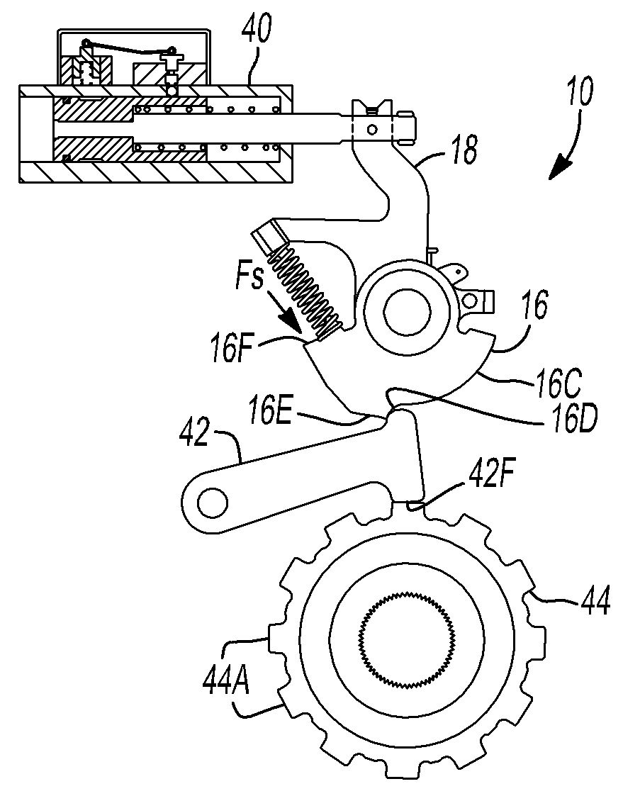
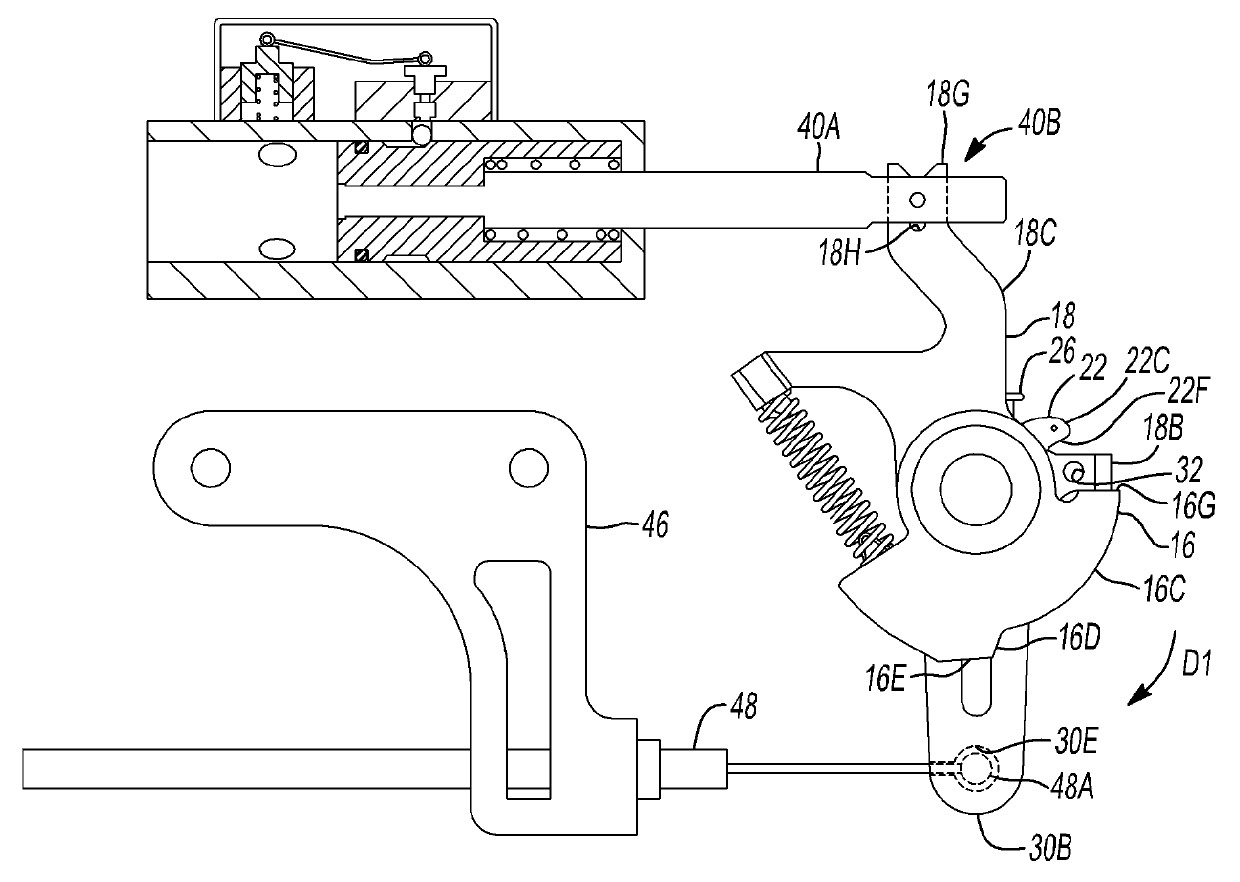
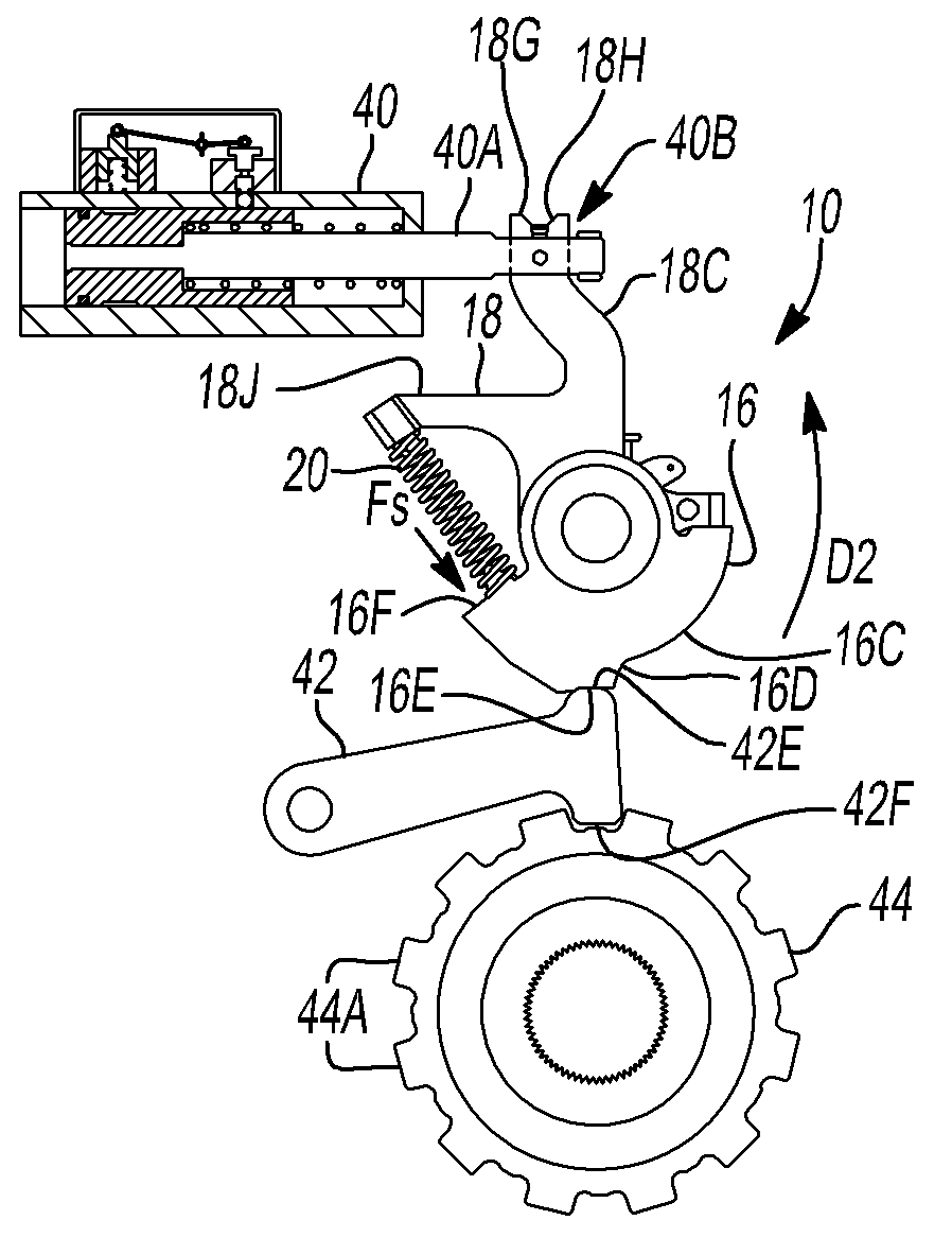
[0100] refer to Figures 1A-1C , a park pawl actuation assembly for a transmission in accordance with the principles of the present invention is generally designated by the reference numeral 10 . The park pawl actuation assembly 10 includes a shaft 12 supported by a transmission housing (not shown), a hub 14, a cam plate 16, a lever plate 18, a compression spring 20, a spring plate 22, a spring 24, first and second Pins 26, 28 and manual release lever 30. More specifically, hub 14 is supported by shaft 12 and is further connected to shaft 12 by pin 26 . The cam plate 16 and the lever plate 18 are rotatably supported by the hub 14 such that the cam plate 16 can move freely relative to the hub 14 and the lever plate 18 . The lever plate 18 is also free to rotate relative to the hub 14 . A compression spring 20 is interposed between the cam plate 16 and the lever plate 18 . The compression spring 20 is arranged to create an angular compressive force between the cam plate 16 a...


PUM


Abstract

A parking pawl actuation assembly for a transmission includes a shaft, a hub member rotatably supported by the shaft, a cam plate and lever plate rotatably supported by the hub member, a first resilient member disposed between the cam plate and the lever plate, and wherein the resilient member applies a rotational force on the cam plate in a first rotational direction when the lever plate is rotated in the first rotational direction, an actuator configured to selectively rotate the lever plate to one of a plurality of positions, and a parking pawl member configured to engage the cam plate and the parking gear of the transmission.

Description

technical field [0001] The present invention relates to an actuated park pawl assembly for an automatic transmission, and more particularly to an actuated park pawl assembly for use with an electronic transmission range selection system. Background technique [0002] The reviews in this section merely provide background information related to the present disclosure and may or may not constitute prior art. [0003] A typical transmission includes a park gear and a pawl to lock the transmission and the rest of the drive train thereby preventing the vehicle from rolling from the original park position, even when the vehicle is parked on a steep grade. Mechanisms designed to engage the park lock to the output shaft of the transmission include direct acting actuators or systems with mechanical couplings to prevent rotation of the output shaft. Including this feature in the transmission adds complexity, weight, cost and packaging size, without increasing the overall performance o...

Claims


Application Information

Patent Timeline
IPC IPC(8): F16H63/34
CPCF16H25/08B60T1/005F16D63/006F16H63/3433F16H63/3416
Inventor C.J.兰迪诺S.W.鲍威尔
Owner GM GLOBAL TECH OPERATIONS LLC
Why Eureka
Try Eureka