High-precision high-acceleration low-frequency sinusoidal vibration system

A high-acceleration and vibration system technology, applied in the direction of measuring devices, instruments, etc., can solve the problems of low vibration frequency accuracy and inability to meet the needs of high-precision inertial instrument testing, and achieve long accuracy retention, convenient use and maintenance, and high transmission efficiency Effect

Inactive Publication Date: 2014-12-03
HARBIN INST OF TECH
View PDF2 Cites 9 Cited by
  • Summary
  • Abstract
  • Description
  • Claims
  • Application Information

AI Technical Summary

Problems solved by technology

[0005] The purpose of the present invention is to provide a high-precision, high-acceleration, low-frequency sinusoidal vibration system, realize high-precision, high-acceleration, low-frequency sinusoidal vibration, make up for the deficiencies of the centrifuge test, improve the flexibility of the research test, and solve the problem of the low-frequency section of the existing vibration table Low accuracy of vibration amplitude and vibration frequency, unable to meet the needs of high-precision inertial instrument testing, etc., to realize the test of high-order error coefficients of inertial instruments

Method used


Image

  • High-precision high-acceleration low-frequency sinusoidal vibration system
  • High-precision high-acceleration low-frequency sinusoidal vibration system
  • High-precision high-acceleration low-frequency sinusoidal vibration system

Examples


Embodiment 1

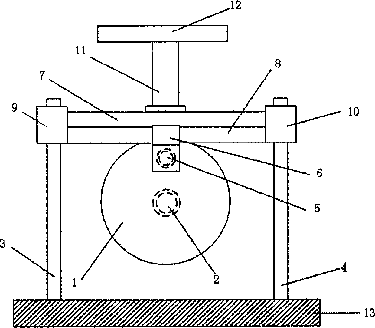
[0018] Such as figure 1 As shown, a high-precision, high-acceleration, low-frequency sinusoidal vibration system includes a rotating motor, a crank plate 1, left and right guide columns 3.4, a crank shaft 5, a horizontal slider 6, a beam 7, a horizontal rolling guide 8, left and right Vertical rolling linear bearing 9.10, column 11, workbench 12 and position sensor, left and right guide post 3.4 are installed on the horizontal base 13, left and right linear bearing 9.10 are respectively installed on the left and right guide post 3.4 and can move along the guide post Move up and down; the two ends of the beam 7 are respectively connected with the left and right vertical rolling linear bearings 9.10, the horizontal rolling guide rail 8 is fixedly connected to the beam 7, the guide rail horizontal slider 6 moves left and right on the horizontal rolling guide rail 8, and the horizontal rolling guide rail 8 is installed on the beam 7 The column 11 and the workbench 12 are installed...

Embodiment 2

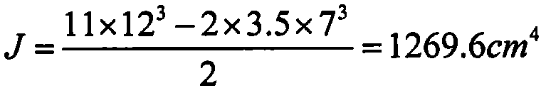
[0042] Calculation of beam deformation affecting vibration amplitude accuracy:

[0043] Rolled aluminum E=6.8×10 10 Pa=6.8×10 6 N / cm 2 , ρ=3g / cm 3

[0044] J = 11 × 12 3 - 2 × 3.5 × 7 3 2 = 1269.6 cm 4

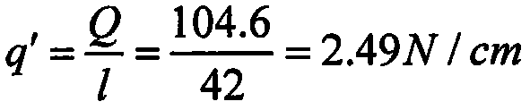
[0045] (1) beam weight

[0046] m=(11×12-2×3.5×7)×42×ρ=10458g, weight Q=104.6N

[0047] Unit length (cm) weight q ′ = Q l = 104.6 42 = 2.49 N / cm

[0048] Install rolling guide rail on beam (SNS 45C) q ′ ′ ...


PUM


Abstract

The invention relates to a high-precision high-acceleration low-frequency sinusoidal vibration system which comprises a rotating motor, a crank disc, a crankshaft, a horizontal rolling guide rail, a vertical rolling linear bearing, an upright post, a worktable, a balance weight and a position sensor, wherein a left guide post and a right guide post are arranged on a base; a left linear bearing and a right linear bearing are respectively arranged on the left guide post and the right guide post and can move up and down on the guide posts; two ends of a transverse beam are respectively connected with the left linear bearing and the right linear bearing; the horizontal rolling guide rail is fixedly connected to the transverse beam; a horizontal guide rail slide block can move from left to right on the horizontal rolling guide rail; and the upright post and the worktable are arranged on the transverse beam. According to the mechanical system, high-precision and high-acceleration low-frequency sinusoidal vibration can be realized, the defects of a centrifuge test are overcome, the flexibility of research trial is improved, the problems that a low-frequency section of the conventional vibration table is low in vibration amplitude and vibration frequency precision, the testing requirements of a high-precision inertia type instrument cannot be met and the like are solved, and a high-order error item coefficient of the inertia type instrument is tested.

Description

technical field [0001] The invention relates to a high-precision, high-acceleration, low-frequency sinusoidal vibration system. Background technique [0002] Calibrating high-order error term coefficients of inertial instruments under overload and high-acceleration test conditions can improve the accuracy of inertial navigation systems, and is a method to solve the problem of "consistency between heaven and earth". There are two methods commonly used at present: one is the precision centrifuge test, and the other is the precision low-frequency line vibration test. [0003] The main problem of the centrifuge test is that the angular velocity is high, which will generate harmful interference torque and will affect the test of the gyroscope and gyro accelerometer. Although it can be solved by installing an inversion platform at one end of the centrifuge, this kind of equipment is very complicated and error-prone. There are many sources, the experiment is difficult, and the cos...

Claims


Application Information

Patent Timeline
Patent Type & Authority Applications(China)
IPC IPC(8): G01C25/00
CPCG01C25/005
Inventor 于志伟曾鸣刘雨任顺清苏宝库
Owner HARBIN INST OF TECH
Why Eureka
Try Eureka