
External wind turbine freezing detector and wind turbine freezing detecting method

A technology of icing detectors and wind turbines, applied in the testing of machines/structural components, testing of mechanical components, instruments, etc., can solve the problems of destroying the blade structure, poor effect, reducing fatigue resistance of components, etc., and achieve adaptability Strong, easy installation, and good versatility

Inactive Publication Date: 2014-12-03
AERODYNAMICS NAT KEY LAB
View PDF3 Cites 16 Cited by
  • Summary
  • Abstract
  • Description
  • Claims
  • Application Information

AI Technical Summary

Problems solved by technology

Its disadvantage is that it is necessary to drill holes in the complete blade, or reserve machining holes during blade production, which will not only bring additional manufacturing and processing burden, but also destroy the integrity of the blade and reduce the fatigue resistance of the components
However, it only judges whether the blade is icing based on the limit icing value of the detector, and cannot give the distribution of icing at different positions of the blade, nor can it meet the corresponding detection requirements
[0010] To sum up, the current wind turbine icing detection methods have poor effects such as manual observation, the way of installing sensors on the blade itself will damage the blade structure, and the existing external detection methods of companies such as Goodrich can only give out whether there is ice or not. Due to the limitations of ice judgment and detailed information such as ice distribution, the detection effect of wind turbine icing is not good.

Method used


Image

  • External wind turbine freezing detector and wind turbine freezing detecting method
  • External wind turbine freezing detector and wind turbine freezing detecting method
  • External wind turbine freezing detector and wind turbine freezing detecting method

Examples


Embodiment 1

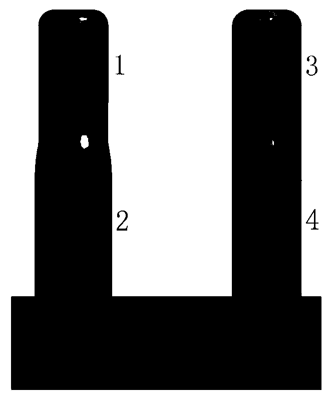
[0066] 1. The present invention firstly designs an external wind turbine icing detector, and its front end is provided with at least two arc ends with different radii. As shown in the figure, two cylinders are designed in this embodiment, and four kinds of arc ends with different radii are designed respectively, as follows Figure 5 , Figure 4 As shown, install 4 sensors. Take the section along the four sensors, respectively as Figure 6-9 As shown, it can be seen that the vicinity of the front edge of the windward section at the four sensors (that is, the arc end) is an arc, and the arc can be other arbitrary shapes after the arc.

[0067] In the present invention, the front end is provided with at least two circular arc ends with different radii, such as Figure 4 As shown in , the vertical arrangement of the first detector and the second detector; the side-by-side arrangement of the arc end where the first detector and the third detector are located can also be adopted....


PUM


Abstract

The invention discloses an external wind turbine freezing detector and a wind turbine freezing detecting method to solve the problems that according to existing wind turbine freezing detecting methods, the shape is designed aiming at the designed wind speed only, and when incoming flow does not meet the designed wind speed condition, errors are large and application is limited. The detector comprises a cylindrical body and sensors, wherein the cylindrical body comprises a front end and a rear end in smooth connection with the front end, at least two arc ends with different radii are arranged at the front end, and the sensors are arranged at the arc ends respectively. The external wind turbine freezing detector is independent of a wind turbine, and freezing data on the external wind turbine freezing detector are extrapolated to obtain the freezing distribution condition on the wind turbine by means of freezing information on the detector and relevant information of a control system of the wind turbine according to a processing system for the relevancy between the meteorological condition, the freezing information on the external wind turbine freezing detector and freezing of the wind turbine. The external wind turbine freezing detector is convenient to install and high in adaptability.

Description

technical field [0001] The invention relates to the field of icing detection, in particular to the field of wind turbine icing detection, in particular to an external wind turbine icing detector and a wind turbine icing detection method. Background technique [0002] With the increasingly serious situation of global energy demand and environmental pollution, the development of renewable energy has become a strategic demand for the development of science and technology in all countries in the world. Because wind energy is easy to obtain, renewable, non-polluting, and has huge potential, it is the most promising large-scale energy in the near future. According to expert estimates, wind power will surpass nuclear power to become the third major power generation source after 2020; it may surpass hydropower in 2050 and become the second largest power generation power source. [0003] my country has a vast territory, complex meteorological conditions, and huge reserves of wind re...

Claims


Application Information

Patent Timeline
IPC IPC(8): G01M13/00
Inventor 易贤周志宏
Owner AERODYNAMICS NAT KEY LAB
Learn More