Metro coin for radio frequency identification

A radio frequency identification and subway coin technology, applied in the field of subway coins, can solve problems such as short service life, poor system stability, and high cost, and achieve the effects of reducing manufacturing costs and maintenance costs, and improving stability and service life

Inactive Publication Date: 2014-12-03
JIANGSU FUNA ELECTRONICS SCI & TECH
View PDF0 Cites 4 Cited by
  • Summary
  • Abstract
  • Description
  • Claims
  • Application Information

AI Technical Summary

Problems solved by technology

[0003] The purpose of the present invention is to overcome the disadvantages of poor system stability, short service life and high

Method used


Image

  • Metro coin for radio frequency identification
  • Metro coin for radio frequency identification

Examples


Embodiment Construction

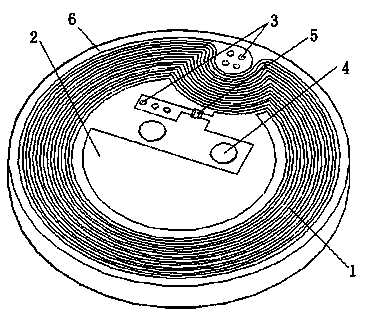
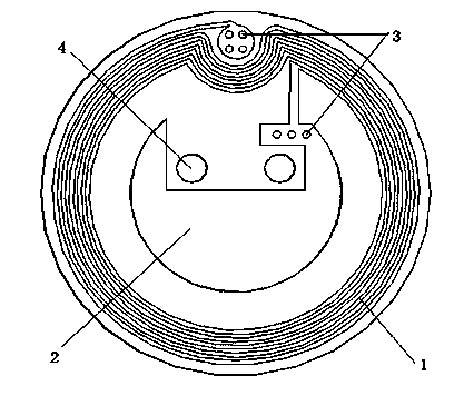
[0012] Below in conjunction with accompanying drawing, the present invention will be further described:

[0013] The high-frequency antenna coil 1 is located on the PCB substrate 6 on the front and back sides of the subway coin, and the high-frequency antenna coil 1 on both sides is electrically connected by a plurality of via holes 3, and the upper and lower layers of copper parallel plates 2 To form an impedance matching flat plate capacitor, the radio frequency chip 5 and the upper parallel plate 2 are located on the same surface, and the radio frequency chip 5 has two pins, one of which is connected to the upper parallel plate 2, and the other pin is connected to the lower parallel plate through the via hole 3. The pole plate 2 is injection-molded into a whole through the fixing hole 4 to inject the high-frequency antenna coil 1 , the upper and lower layers of copper parallel pole plates 2 and the radio frequency chip 5 .


PUM


Abstract

The invention provides a metro coin for radio frequency identification. The metro coin comprises a radio frequency chip, a PCB substrate and radio frequency antenna coils arranged on the PCB substrate. The metro coin further comprises an impedance matching capacitor formed by upper and lower two parallel polar plates. The radio frequency antenna coils are arranged at the two sides of the metro coin and are in electrical connection through via holes; the radio frequency chip is arranged on the same surface with the upper parallel polar plate; and the radio frequency chip has two pins, one pin being connected with the upper parallel polar plate, and the other pin being connected with the lower two parallel polar plate through the via holes.

Description

technical field [0001] The invention relates to an anti-metal electronic tag for radio frequency device identification, in particular to a subway coin used for radio frequency device identification. Background technique [0002] In order to achieve reflection-free transmission or maximum power transmission of radio frequency signals, impedance matching of the radio frequency system is required. At present, the subway coins used for radio frequency identification generally use external capacitors to achieve impedance matching. Due to the damage of the external capacitors, it is easy to cause the failure of the subway coins, which greatly reduces the stability and service life of the radio frequency identification system, and also improves the product manufacturing to a certain extent. and usage costs. Contents of the invention [0003] The purpose of the present invention is to overcome the disadvantages of poor system stability, short service life and high cost caused by ...

Claims


Application Information

Patent Timeline
IPC IPC(8): G06K19/07H01Q1/22
Inventor 陶福平
Owner JIANGSU FUNA ELECTRONICS SCI & TECH
Why Eureka
Try Eureka