
Method for reducing residual austenite in high-alloy steel

A technology of retained austenite and high alloy steel, applied in the field of reducing retained austenite in high alloy steel, can solve the problems of complicated operation, increase of unknown factors, lack of universality, etc., to achieve convenient operation, improve stability and Service life, the effect of reducing the crack initiation source

Inactive Publication Date: 2020-09-25
TSINGHUA UNIV
View PDF4 Cites 0 Cited by
  • Summary
  • Abstract
  • Description
  • Claims
  • Application Information

AI Technical Summary

Problems solved by technology

[0005] In the traditional heat treatment method described in Patent 1, the heat treatment of materials is generally accompanied by complex changes in structure and phase. Different heat treatment processes have different mechanisms of action, and have certain limitations for different types of materials.
Moreover, the dimensional accuracy of aerospace bearing materials is extremely high, and its heat treatment process is relatively mature and complicated. The use of heat treatment process to reduce the residual austenite in the bearing steel material is often accompanied by changes in other structures and phases, and uncontrollable and unknown factors increase. In addition, this method is relatively complicated to operate and not universal

Method used


Image

  • Method for reducing residual austenite in high-alloy steel
  • Method for reducing residual austenite in high-alloy steel
  • Method for reducing residual austenite in high-alloy steel

Examples


Embodiment Construction

[0045] Embodiments of the present invention are described in detail below, examples of which are shown in the drawings, wherein the same or similar reference numerals designate the same or similar elements or elements having the same or similar functions throughout. The embodiments described below by referring to the figures are exemplary only for explaining the present invention and should not be construed as limiting the present invention.

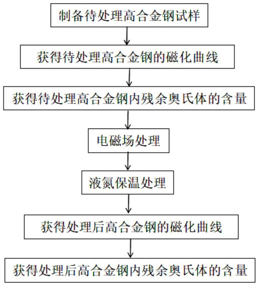
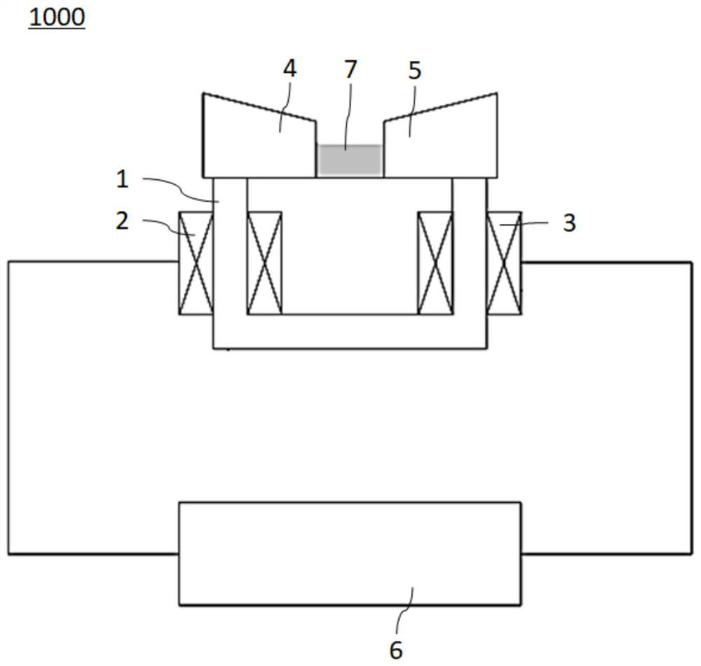
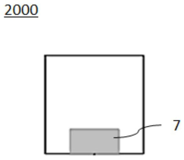
[0046] Combine below Figure 1 to Figure 15 A method for reducing retained austenite in high alloy steel according to an embodiment of the present invention will be described.

[0047] Such as Figure 1 to Figure 15 As shown, the method for reducing retained austenite in high alloy steel according to an embodiment of the present invention includes the following steps:

[0048] Electromagnetic field treatment: place the high-alloy steel 7 to be treated in the electromagnetic field generated by the magnetization device 1000 at room tempe...


PUM

PropertyMeasurementUnit
Lengthaaaaaaaaaa
Widthaaaaaaaaaa
Heightaaaaaaaaaa

Abstract

The invention discloses a method for reducing residual austenite in high-alloy steel. The method comprises the steps of electromagnetic field treatment and liquid nitrogen heat-preservation treatment,wherein under the normal temperature, the to-be-treated high-alloy steel is placed into an electromagnetic field generated by a magnetizing device, magnetically-induced phase transition is caused according to the magnetically-induced clearance channeling mechanism, and thus the residual austenite in the high-alloy steel is converted into martensite; and the high-alloy steel subjected to electromagnetic field treatment is placed into a closed container containing liquid nitrogen to be subjected to liquid nitrogen heat-preservation treatment so as to prompt the residual austenite in the high-alloy steel subjected to electromagnetic field treatment to continue being converted into the martensite. According to the method for reducing the residual austenite in the high-alloy steel, part of themetastable residual austenite in the high-alloy steel can be prompted to be converted into the martensite, the size stability of a high-alloy steel material is improved, the service life of the high-alloy steel material is prolonged, crack starting sources are reduced, and the advantages of environmental friendliness, energy conservation, convenient and rapid operation and high timeliness are achieved.

Description

technical field [0001] The invention relates to the technical field of high-alloy steel residual austenite phase transformation, in particular to a method for reducing high-alloy steel residual austenite. Background technique [0002] In the process of heat treatment, quenching and tempering of high alloy steel materials, due to insufficient cooling and transformation of austenite, there will inevitably be a certain amount of retained austenite. The retained austenite is unstable at room temperature and is easy to transform during use. It is a martensitic structure, and the phase transformation of the material heat treatment is often a first-order phase transformation accompanied by volume and size changes. Since the specific volume of retained austenite is smaller than that of martensite, the phase transformation process will lead to an increase in the size of the material, especially affecting the precision of precision materials such as bearings, which in turn will affect...

Claims


Application Information

Patent Timeline
IPC IPC(8): C21D1/04C21D6/04
CPCC21D1/04C21D6/04C21D2211/008
Inventor 王恒李克俭马雷季文吴瑶蔡志鹏
Owner TSINGHUA UNIV
Learn More