Mobile radioactive source supervision system and method

A monitoring system and radioactive source technology, applied in the field of monitoring system for mobile radioactive sources, can solve the problems of low degree of informatization, lack of corporate behavior to be incorporated into the environmental protection scientific management system, illegal opening, etc., to achieve comprehensive management functions and clear system structure. , the effect of good system integrity

Inactive Publication Date: 2014-12-03
HANGZHOU XIANGTING TECH
View PDF6 Cites 8 Cited by
  • Summary
  • Abstract
  • Description
  • Claims
  • Application Information

AI Technical Summary

Problems solved by technology

[0004] 1. The radioactive source storage tank has no tamper-proof function and can be easily opened illegally
[0005] 2. Simple technical means: simple dose and location monitoring, lack of new technology applications, no scientific and reasonable solutions for multiple sources in one enterprise, no effective and reliable monitoring means for the movement of radioactive sources, and lack of incorporating corporate behavior into environmental protection scientific management Technical implementation of the system
[0006] 3. Simple management mode: low degree of informatization, simple system structure, lack of regional macro management concepts and innovation models, simple monitoring of objects, and failure to incorporate corporate behavior into an effective regulatory system

Method used


Image

  • Mobile radioactive source supervision system and method
  • Mobile radioactive source supervision system and method
  • Mobile radioactive source supervision system and method

Examples


Embodiment 1

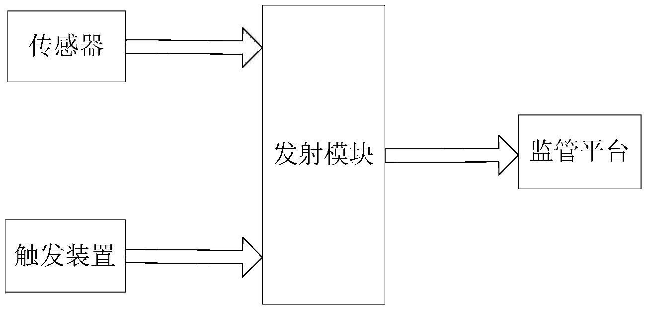
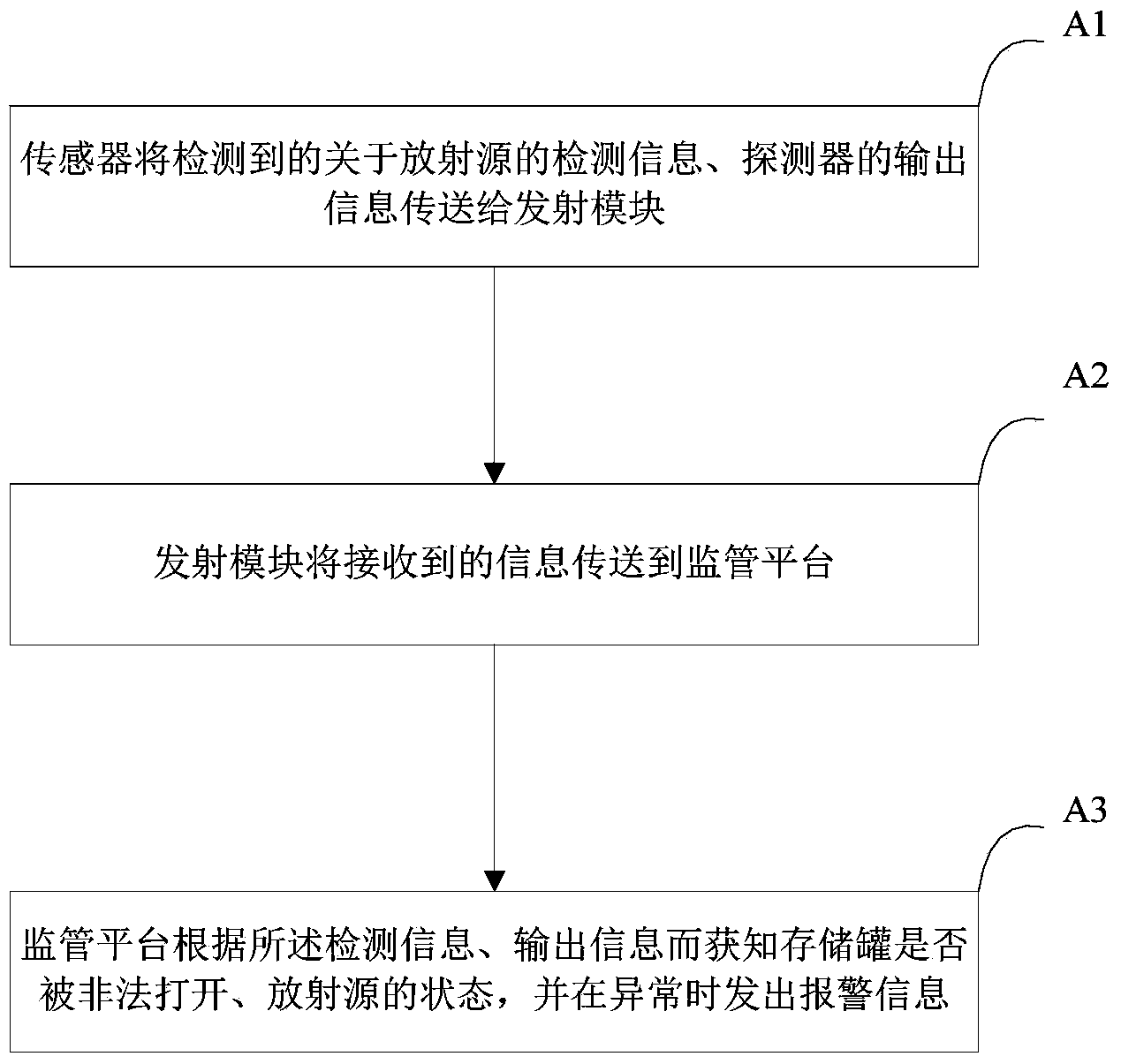
[0061] figure 1 A basic structural diagram of the mobile radioactive source monitoring system in Embodiment 1 of the present invention is schematically given. like figure 1 As shown, during the movement of the radioactive source, the radioactive source is placed in the storage tank, and the storage tank includes a tank body and a cover; the mobile radioactive source supervision system includes:

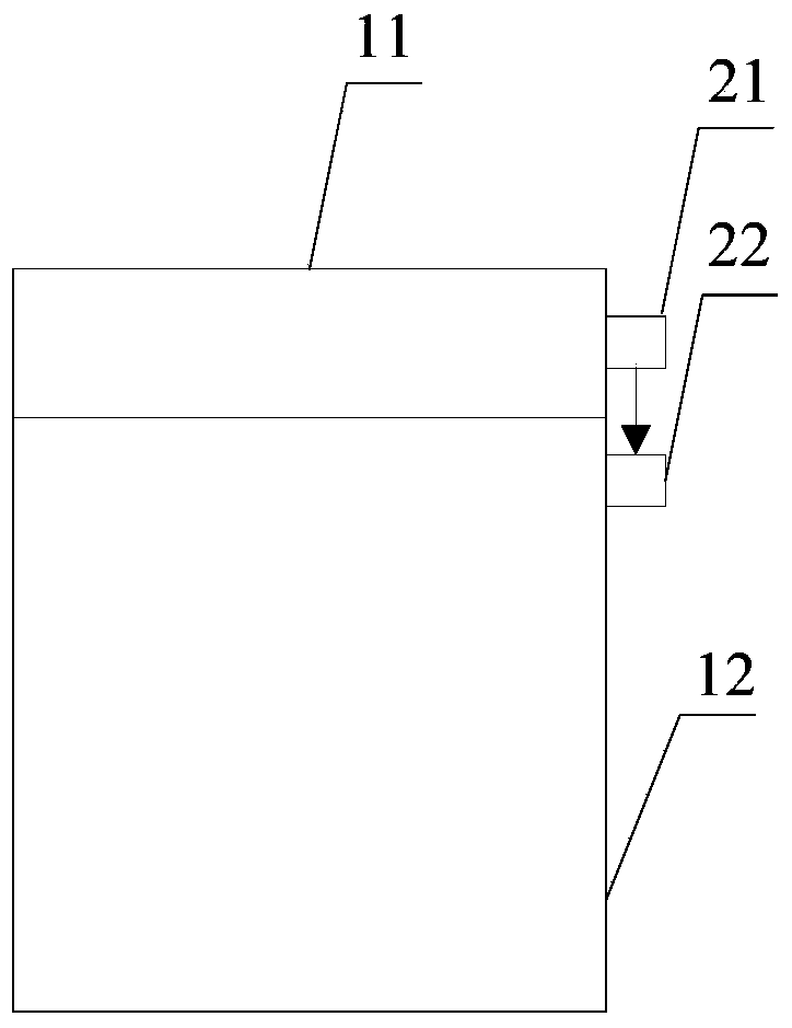
[0062] One or more trigger devices, such as figure 2 As shown, the triggering device includes an infrared light source 21 and a detector 22. The infrared light source 21 is arranged on the cover 11, and the detector 22 is arranged on the tank body 12 for receiving the light emitted by the light source. The detector The output terminal is connected to the transmitter module. When the storage tank is illegally opened, the signal received by the detector in the trigger device is abnormal, indicating that the storage tank is illegally opened, and an alarm needs to be prompted. A trig...

Embodiment 2

[0073] Figure 4 The basic structural diagram of the mobile radioactive source monitoring system in Embodiment 2 of the present invention is schematically given, as Figure 4 As shown, during the movement of the radioactive source, the radioactive source is placed in the storage tank, and the storage tank includes a tank body and a cover; the mobile radioactive source supervision system includes:

[0074] One or more trigger devices, such as Figure 5 , 6 As shown, the triggering device includes an infrared light source 21, a detector 22, and an optical fiber 23. The infrared light source 21 and the detector 22 are all arranged on the tank body 12, and the two ends of the optical fiber 23 are respectively connected to the light source 21 and the detector 22. The middle part bypasses the column 24 on the cover body 11, and the optical fiber 23 is in a tensioned state, specifically: the optical fiber 23 bypasses the column 241, but is blocked by the blocking body 242, thereby ...

Embodiment 3

[0095] The mobile radioactive source monitoring system of Embodiment 3 of the present invention is different from Embodiment 2 in that:

[0096] The mobile radioactive source monitoring system further includes: a radio station, using the information transmitting and receiving functions of the radio station to replace the above-mentioned transmitting module and receiving module, so as to be used in areas without civil public network or poor network.

[0097] like Figure 8 As shown, a cylinder 241 is set on the cover 11, but no stopper is provided. The upper end of the cylinder is provided with a groove 243, and the optical fiber 23 is wound in the groove 243 to prevent the optical fiber from being illegally moved. The function is the same as the stopper.

[0098] Of course, the above-mentioned radio station can also coexist with the transmitting module and the receiving module. When there is a public network area, the transmitting module and the receiving module are used; when...


PUM


Abstract

The invention provides a mobile radioactive source supervision system. A storage tank of radioactive sources comprises a tank body and a cover body. One or more trigger devices are arranged on the tank body and the cover body, the trigger device comprises a signal source and a detector, the output end of the detector is connected with one or more transmitting modules. One or more sensors are used for transmitting detected detection information related to the one or more radioactive sources to the one or more transmitting modules. The detection information comprises radiation dosages of the one or more radioactive sources. The one or more transmitting modules are used for transmitting the received detection information and output information of the detector to a supervision platform. The supervision platform is used for enabling a user to know whether the storage tank is opened abnormally or not according to the received output information of the detector, monitoring the states of the one or more radioactive sources in real time according to the received detection information, and sending out alarm information when abnormities exist. The mobile radioactive source supervision system has the advantages of being comprehensive in function, low in cost, convenient to achieve and the like.

Description

technical field [0001] The invention relates to a monitoring system and method, in particular to a monitoring system and method for mobile radioactive sources. Background technique [0002] The traditional monitoring of radioactive sources only monitors the radioactive intensity of radioactive sources, that is, dose rate monitoring. The method is to install detectors at a certain distance from the radioactive sources and transmit them to the central controller through data lines. Some more complex systems will add video surveillance, radioactive source coordinate monitoring (GPS), etc. At the same time, the data is transmitted to the monitoring center by the combination of IE network data transmission, wireless microwave data transmission and GPRS data transmission. [0003] The above radioactive source monitoring system has many deficiencies, such as: [0004] 1. The radioactive source storage tank has no tamper-proof function and can be easily opened illegally. [0005]...

Claims


Application Information

Patent Timeline
Patent Type & Authority Applications(China)
IPC IPC(8): G08B21/12
Inventor 何帅兴刘岳洲葛永恒蓝国华何雄太
Owner HANGZHOU XIANGTING TECH
Why Eureka
Try Eureka