Digital multi-beam antenna

A digital multi-beam and antenna technology, applied in the direction of antennas, electrical components, etc., can solve the problems of multi-beam antenna complex structure, poor anti-interference, high cost, etc., to achieve suitable for mass production, strong anti-interference ability, and low production cost low effect

Inactive Publication Date: 2014-12-03
WUHU HANGFEI SCI & TECH
View PDF3 Cites 1 Cited by
  • Summary
  • Abstract
  • Description
  • Claims
  • Application Information

AI Technical Summary

Problems solved by technology

[0005] At present, the multi-beam antenna technology in the prior art has complex structure, high production cost, and poor anti-interference, which cannot meet the development needs of modern society.

Method used


Image

  • Digital multi-beam antenna
  • Digital multi-beam antenna

Examples


Embodiment Construction

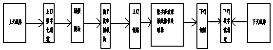
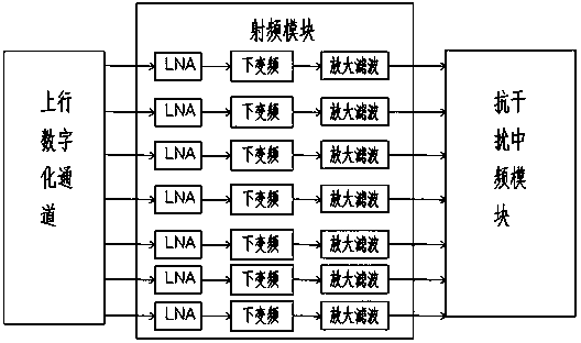
[0015] Such as figure 1 , figure 2 As shown, a digital multi-beam antenna is mainly composed of an upper and lower antenna array, an up and down digital channel, a digital multi-beam forming multiple signal processor, and a communication signal processor. The output end of the upper antenna array is connected to the input end of the uplink digital channel , the output of the uplink digital channel is connected to the input of the RF module, the output of the RF module is connected to the input of the anti-jamming IF module, the output of the anti-jamming IF module is connected to the input of the uplink, and the output of the uplink is connected to the digital In the multi-beam forming multiplier processor, the digital multi-beam forming multiplier processor is output to the downlink input terminal, the downlink is input to the downlink digital channel, the lower antenna array input terminal is connected to the downlink digital channel, and the radio frequency The module is ...


PUM


Abstract

Disclosed is a digital multi-beam antenna which mainly includes upper and lower antenna arrays, uplink and downlink digital channels, a digital multi-beam formation multiplier processor and a communication signal processor. An output end of the uplink digital channel is connected to an input end of a radio frequency module. An output end of the radio frequency module is connected to an input end of an anti-interference intermediate frequency module. An output end of the anti-interference intermediate frequency module is connected to an input end of an uplink. An output end of the uplink is connected to the digital multi-beam formation multiplier processor. The digital multi-beam formation multiplier processor outputs to an input end of an downlink and the downlink inputs to the downlink digital channel. An input end of the lower antenna array is connected to the downlink digital channel. Through setting of the radio frequency module, the digital multi-beam antenna is enabled to have frequency conversion, amplification, filtering and intermediate frequency output functions and is excellent in channel uniformity, higher in anti-interference capability, and more suitable for use demands of modern society and people; and the digital multi-beam antenna is also comparatively low in manufacturing cost and suitable for mass production.

Description

technical field [0001] The invention relates to antenna structure technology, in particular to a digital multi-beam antenna. Background technique [0002] According to the structural form, multi-beam antennas can be roughly divided into two basic forms: reflective and direct-beam; according to the beamforming method, it can be attributed to analog multi-beam forming and digital multi-beam forming: each form of antenna can work in both receiving and transmitting. mode. [0003] The direct-beam multi-beam antenna uses a beamformer in the form of a power combining distribution network, etc., by controlling the phase of the antenna unit, in different directions, the electromagnetic wave satisfies the same "spatial phase difference" and "in-array phase difference", thereby simultaneously forming Multiple beams in different directions. Direct-beam multibeam antennas can be used analog or digitally to form a large number of wide-angle scanning beams at RF, IF, or baseband...

Claims


Application Information

Patent Timeline
Patent Type & Authority Applications(China)
IPC IPC(8): H01Q23/00H01Q3/24
Inventor 朱倩檀剑飞舒航王威徐盼盼陈坤
Owner WUHU HANGFEI SCI & TECH
Why Eureka
Try Eureka