Broadband microwave and millimeter wave receiver

A millimeter wave and receiver technology, applied in the field of microwave and millimeter wave testing, can solve the problems of large circuit and large circuit insertion loss, and achieve the effect of high operating frequency, good channel consistency, and large instantaneous bandwidth

Inactive Publication Date: 2017-12-22
THE 41ST INST OF CHINA ELECTRONICS TECH GRP
View PDF6 Cites 0 Cited by
  • Summary
  • Abstract
  • Description
  • Claims
  • Application Information

AI Technical Summary

Problems solved by technology

[0003] In the prior art, the direction of the RF connector is perpendicular to the plane of the microstrip circuit. Usually, the inner conductor of the connector or the inner conductor of the glass terminal is vertically interconnected with the microstrip line through a gold tape or a gold mesh, but the higher the frequency, the less vertically interconnected. The greater the influence of continuity on the circuit, the greater the insertion loss of the circuit

Method used


Image

  • Broadband microwave and millimeter wave receiver
  • Broadband microwave and millimeter wave receiver
  • Broadband microwave and millimeter wave receiver

Examples


Embodiment Construction

[0024] Below in conjunction with accompanying drawing and specific embodiment the present invention is described in further detail:

[0025] The object of the present invention is to provide a kind of broadband microwave millimeter wave receiver, has following characteristics:

[0026] a. The RF input adopts a structure that replaces the vertical interconnection, which reduces the input insertion loss of high-frequency signals;

[0027] b. It has a wide frequency band (8GHz ~ 40GHz) receiving range;

[0028] c. The frequency mixing method adopts the combination of high local vibration and low local vibration, which effectively reduces the design difficulty of the local vibration unit;

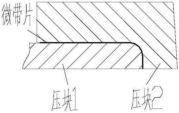
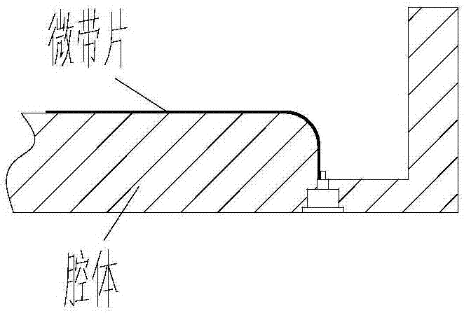
[0029] In a, the soft dielectric substrate (microstrip sheet) is used to bond to the vertical surface with radians. The soft dielectric substrate can use Rogers 5870 copper clad laminate or Rogers 5880 copper clad laminate, and it is bonded with conductive adhesive.

[0030] During design, a ...


PUM


Abstract

The invention discloses a broadband microwave and millimeter wave receiver and belongs to the field of a microwave millimeter wave test. The broadband microwave and millimeter wave receiver comprises a radio frequency unit, a switch filter unit and a local oscillator unit. A radio frequency input end, adopting a soft medium substrate, of the switch filter unit is adhered on a vertical surface with an arched structure by bending 90 degrees; the radio frequency unit generates a radio frequency signal and inputs the radio frequency signal into the switch filter unit; and the radio frequency signal output by the switch filter unit and a local oscillator signal generated by the local oscillator unit are subjected to frequency mixing in a high local oscillator and low local oscillator combination mode, and an intermediate frequency signal is output. The broadband microwave and millimeter wave receiver has the advantages of relatively high working frequency, a low noise coefficient, a high instant bandwidth, high channel consistency, high integration degree and high direction finding precision and angle resolution.

Description

technical field [0001] The invention belongs to the field of microwave and millimeter wave testing, in particular to a broadband microwave and millimeter wave receiver. Background technique [0002] The reception and processing of radar electromagnetic radiation signals has always been the key technology and research hotspot in the field of electronic countermeasures and passive guidance. , A number of measures such as extended operating frequency, frequency agility, frequency diversity, and intra-pulse modulation have been generally adopted, and radar decoys are equipped. In order to adapt to changes in radar technology, passive guidance systems need to have higher operating frequency and instantaneous bandwidth. [0003] In the prior art, the direction of the RF connector is perpendicular to the plane of the microstrip circuit. Usually, the inner conductor of the connector or the inner conductor of the glass terminal is vertically interconnected with the microstrip line t...

Claims


Application Information

Patent Timeline
Patent Type & Authority Applications(China)
IPC IPC(8): H04B1/08H04B1/16
CPCH04B1/08H04B1/16
Inventor 时国盛王钊张文兴逄春辉韩俊辉赵建鹏
Owner THE 41ST INST OF CHINA ELECTRONICS TECH GRP
Why Eureka
Try Eureka