Salient-pole pole-changing synchronous motor

A technology of synchronous motors and salient poles, which is applied in the direction of synchronous motors for single-phase current, magnetic circuit shape/style/structure, magnetic circuit rotating parts, etc., which can solve the problem of reduced material utilization rate, low space or material utilization rate , It is difficult to accurately determine the magnetic pole position and other issues

Inactive Publication Date: 2014-12-03
SHANGHAI ELECTRIC TIMAC
View PDF0 Cites 1 Cited by
  • Summary
  • Abstract
  • Description
  • Claims
  • Application Information

AI Technical Summary

Problems solved by technology

[0006] However, this polar diagram is actually only a rough analysis tool, and it is difficult to accurately determine the position of the magnetic poles, or the size and spacing of each magnetic pole.
The current structure of unequal distribution of poles also has

Method used


Image

  • Salient-pole pole-changing synchronous motor
  • Salient-pole pole-changing synchronous motor
  • Salient-pole pole-changing synchronous motor

Examples


Embodiment 1

[0046] Embodiment 1, method steps are as follows:

[0047] 1. Select the number of pole pairs p of the front pole and the rear pole 1 =12 and p 2 =10;

[0048] 2. Select the dense slot coefficient k=4, then the virtual slot number of the rotor is Z=2kp 1 =96

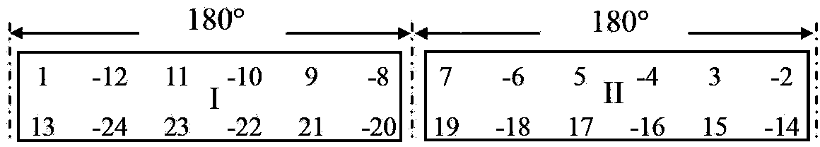
[0049] 3. According to the selected variable front pole p 1 and variable posterior pole p 2 The number of pole pairs, and the number of virtual slots Z, draw the variable front pole p 1 Slot number phase diagram and post pole p 2 Slot number phase diagram, such as image 3 with Figure 4a As shown, only the 180° range is drawn;

[0050] 4. Before changing pole p 1 Select the second column on the slot number phase diagram as the original magnetic pole column, see image 3 , the slot number contained in this column also represents the initial position of the original magnetic pole before the pole change;

[0051] 5. Select the first column and the third column adjacent to the original magnetic pole column as th...

Embodiment 2

[0056] Embodiment 2, in 1, can make k=5, at this moment Z=2kp 1 =120, a pole-changing scheme obtained, which is in the number of pole pairs p 1 =12 and p 2 =10 slot number phase distribution respectively as follows Figure 7a with Figure 7b as shown, Figure 8 A schematic diagram of the magnetic pole arrangement at this time. Still in accordance with general custom, Figure 8 The middle excitation poles are re-numbered according to the order of the slot numbers, that is, the numbers 1, 2, ..., 20 respectively represent the slot numbers 111, 116, 1, 7, 15, 21, 26, 31, 37, 45 in the figure , 51, 56, 61, 67, 75, 81, 86, 91, 97, 105. In the figure, the excitation poles still have unequal spacing. It can be seen that the distribution of magnetic poles along the rotor circumference is similar when k=5 and k=4, but the spacing is different. In the figure, for larger than normal polar distance k=τ 1 The intervals are still marked with 4 widths respectively The position of t...


PUM


Abstract

The invention relates to the motor technical field and especially to a salient-pole pole-changing synchronous motor. The salient-pole pole-changing synchronous motor comprises a stator three-phase winding with two different numbers of pole-pairs p1 and p2, wherein the p1 is greater than p2. Magnetic poles arranged on a rotor are configured in salient-pole non-equidistant structure and have same sizes and widths. A DC excitation coil is wound around each magnetic pole. All the magnetic poles are divided into two groups. When the directions of current flowing through the excitation coils in the two groups are same, the number of pole-pairs of the rotor is p1. When the directions of current flowing through the excitation coils in the two groups are opposite, the number of pole-pairs of the rotor is p2. Based on a concept of virtual multiple grooves, a salient-pole rotor is converted into a non-salient-pole rotor by means of a groove number phase diagram so as to be analyzed such that a novel design principle is formed. Therefore, a clear and visualized basis is provided for the establishment of a pole-changing scheme.

Description

technical field [0001] The invention relates to the technical field of motors, in particular to a pole-changing synchronous motor. Background technique [0002] There are many ways to adjust the speed of synchronous motors, but the pole-changing speed regulation is the most simple and easy. Different from the asynchronous motor, the pole-changing speed regulation of the synchronous motor needs to change the number of pole pairs of the stator winding and the rotor winding at the same time. For the pole changing problem of the stator winding of the synchronous motor, in principle, it is the same as the pole changing of the stator winding of the asynchronous motor, and its research has been quite in-depth. [0003] Synchronous motors can be divided into hidden pole type and salient pole type according to the different rotor structures. The air gap of the hidden pole machine is uniform, while the air gap of the salient pole machine is non-uniform. In practical applications, sy...

Claims


Application Information

Patent Timeline
IPC IPC(8): H02K19/10H02K1/24H02K3/12
Inventor 吕滢熙李盾张东生胡康银
Owner SHANGHAI ELECTRIC TIMAC
Why Eureka
Try Eureka