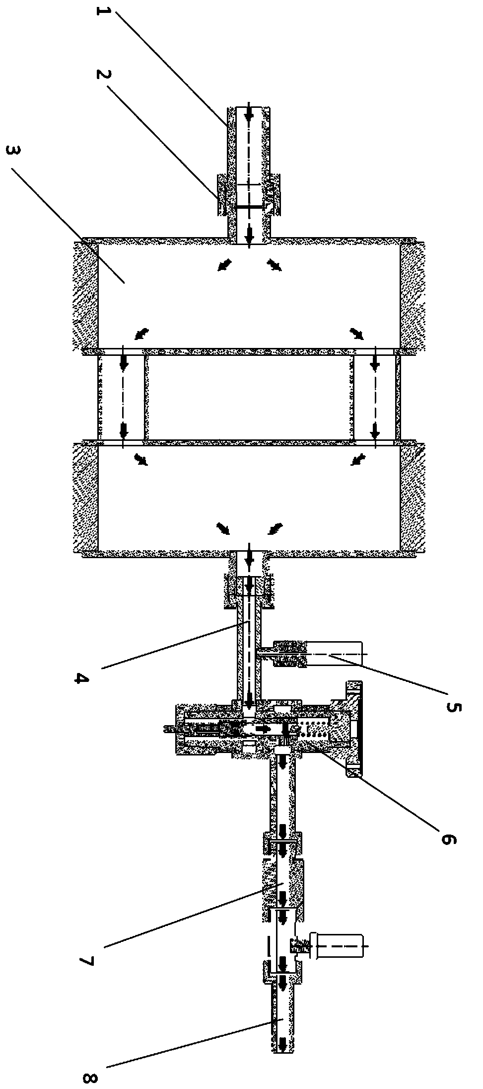
Miniaturized constant-flow water distribution structure and detection device with same
A technology for structural detection and water distribution, which is applied in the application of electromagnetic flowmeters to detect fluid flow, fluid pressure measurement using capacitance changes, and production of fluids. Achieve the effect of ensuring the effect of downhole use, alleviating the variation of stratified water volume, and being convenient and reliable for on-site use
- Summary
- Abstract
- Description
- Claims
- Application Information
AI Technical Summary
Problems solved by technology
Method used
Image
Examples
Embodiment 1
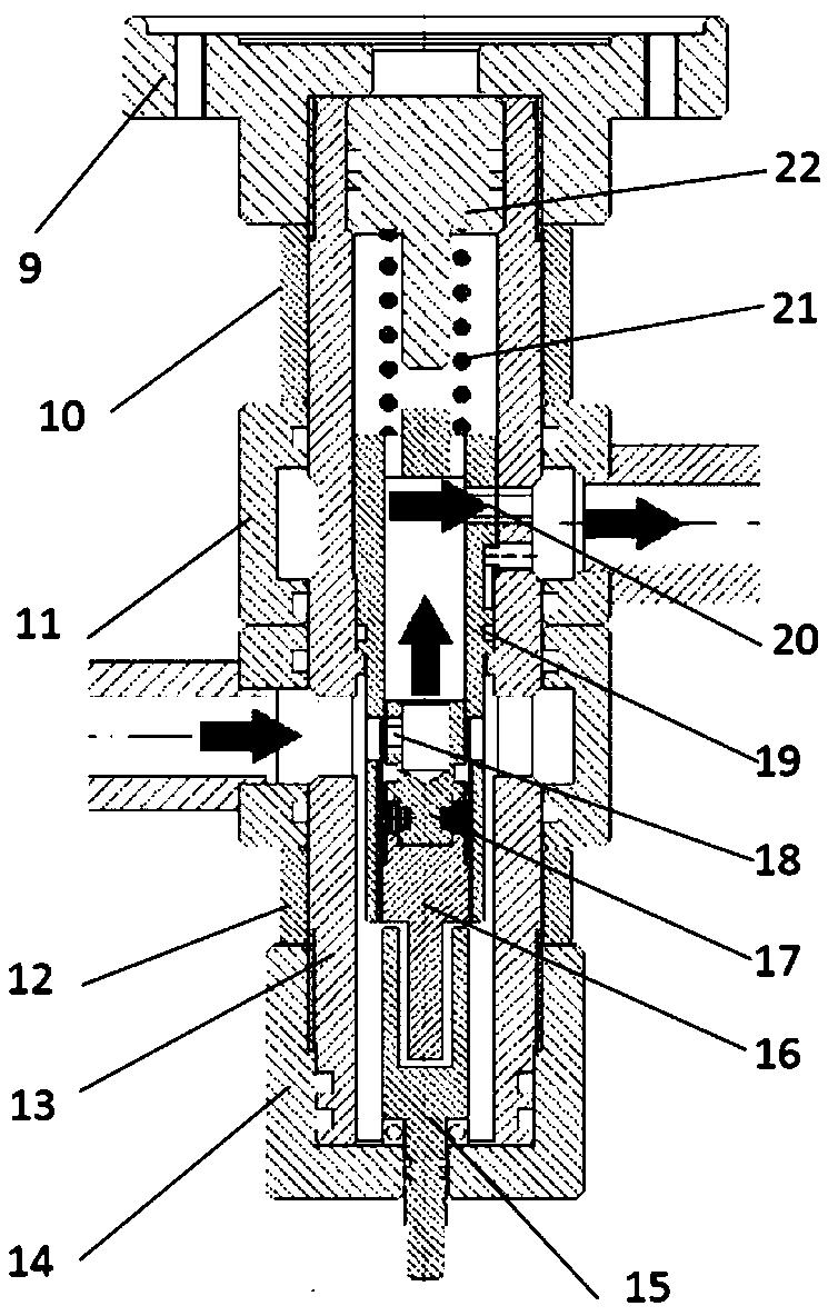
[0038] Please refer to figure 2 , which shows a schematic diagram of the overall structure of a miniaturized constant-flow water distribution structure of the present invention, which includes:
[0039] a pipe body, the pipe body has an overflow channel;
[0040] The constant current elastic part 21, the constant current elastic part 21 includes;
[0041] a body with a compressible pressure chamber inside;
[0042] elastic part;
[0043] transmission components; and
[0044] The transmission part is located at the opening of the pressure chamber, the elastic part is located in the pressure chamber, one end of the elastic part is connected to the inner wall of the pressure chamber, and the other end is connected to the transmission part, and the transmission part passes through the The elastic part can extend or retract the pressure chamber;
[0045] Valve part 19;
[0046] The inside of the flow channel communicates with the outer surface of the transmission part of the...
Embodiment 2
[0052] Further, please refer to figure 2 , another embodiment of a miniaturized constant-flow water distribution structure of the present invention, the first water inlet and the first water outlet of the flow channel communicate with the outside world, and the valve part 19 is a movable sliding sleeve, and the inside of the movable sliding sleeve There is a second flow passage, the second water inlet 18 and the second water outlet 20 of the second flow passage communicate with the outside world, the movable sliding sleeve is located in the flow passage, the movable sliding sleeve is connected to the The overcurrent channel is slidingly connected, the first water inlet of the overcurrent channel communicates with the first water outlet through the second water inlet 18 and the second water outlet 20, and the transmission direction of the transmission part is in line with the movable sliding sleeve. The sliding direction is the same, and the transmission part is in transmissio...
Embodiment 3
[0058] Further, please refer to figure 2 , another embodiment of a miniaturized constant flow water distribution structure of the present invention, the opening size of the first water inlet is equivalent to the opening size of the second water inlet 18;
[0059] The opening size of the first water outlet is equivalent to the opening size of the second water outlet 20 .
[0060] In the above embodiment,
[0061] The opening size of the first water inlet is equivalent to the opening size of the second water inlet 18, and the opening size of the first water outlet is equivalent to the opening size of the second water outlet 20. Finally, the matching parts of the constant-flow elastic part 21 and the valve part 19 can accurately control the pressure in the flow passage, and make the flow-control effect of the miniaturized constant-flow water distribution structure more accurate.
PUM
 Abstract
Description
Claims
Application Information
 - R&D
- Intellectual Property
- Life Sciences
- Materials
- Tech Scout
- Unparalleled Data Quality
- Higher Quality Content
- 60% Fewer Hallucinations
Browse by: Latest US Patents, China's latest patents, Technical Efficacy Thesaurus, Application Domain, Technology Topic, Popular Technical Reports.
© 2025 PatSnap. All rights reserved.Legal|Privacy policy|Modern Slavery Act Transparency Statement|Sitemap|About US| Contact US: help@patsnap.com


