
High-strength high-performance filter element

A high-performance, high-strength technology, applied in the direction of fixed filter element filter, filtration separation, chemical instruments and methods, etc., can solve the problems of reducing the service life of the transmission system, reducing the filtration precision of the filter, the impact of filtration precision and efficiency, etc. , to achieve the effect of increasing the flow performance, increasing the filter contact area, and easy processing

Inactive Publication Date: 2014-12-10
SOUTH CHINA UNIV OF TECH
View PDF5 Cites 5 Cited by
  • Summary
  • Abstract
  • Description
  • Claims
  • Application Information

AI Technical Summary

Problems solved by technology

The filter element is the element that actually filters pollutants. During use, the micro particles deposited on the filter paper continue to accumulate, block the filter holes, and reduce the filtration efficiency; as the intercepted pollutants increase, the pressure drop generated by the oil passing through the filter element increases. , when a certain part of the filter paper is crushed, the microparticles in the liquid will directly pass through there, reducing the filtration accuracy of the filter, and will be brought into the friction surface of the kinematic pair with the flow of hydraulic oil in the system, accelerating Wear and tear of parts reduces the service life of the transmission system
[0007] In addition, in the existing technology, the filter layer that plays a filtering role is filter paper, but the filter paper is easily broken and damaged during use, and the filtration accuracy and efficiency are affected to a certain extent; the strength of the central tube that plays a supporting role is low, Liquid permeability is not high

Method used


Image

  • High-strength high-performance filter element
  • High-strength high-performance filter element
  • High-strength high-performance filter element

Examples


Embodiment Construction

[0031] The present invention will be further described in detail below with reference to the drawings and embodiments.

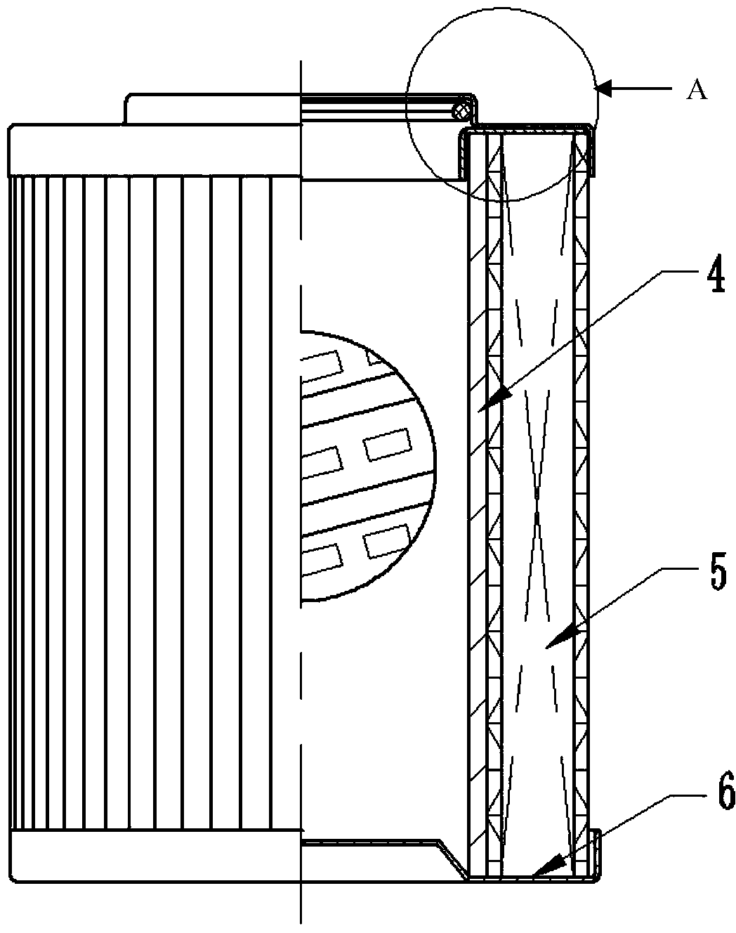
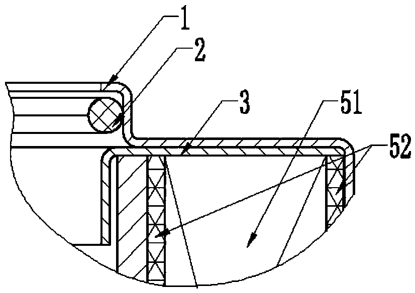
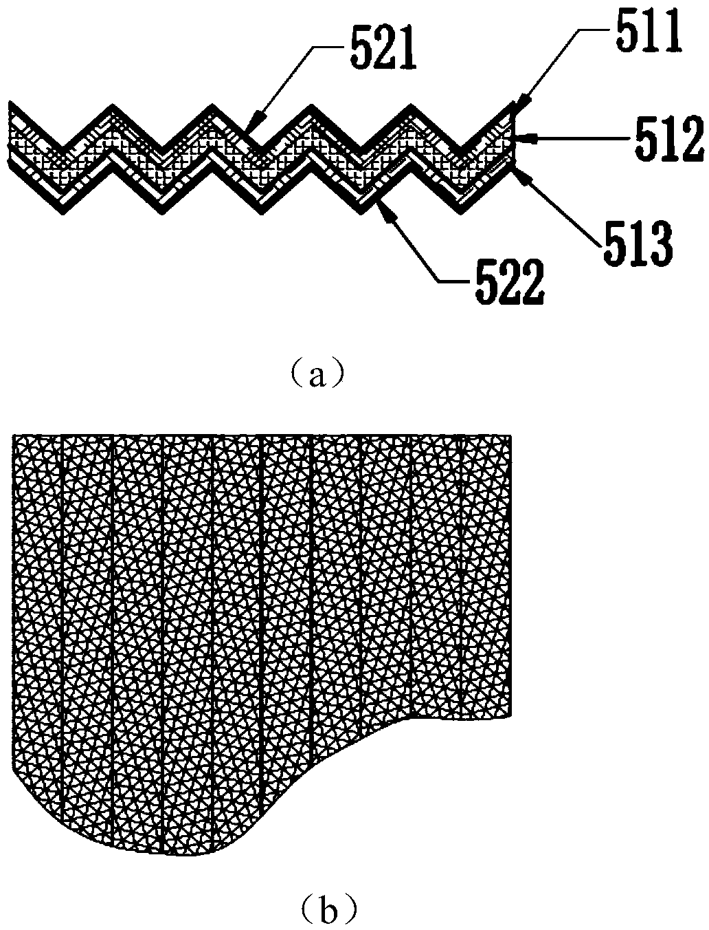
[0032] Such as Figure 1 ~ Figure 4 As shown, a high-strength and high-performance filter element includes an upper end cover (1), a lower end cover (6), a center tube (4), and a filter cartridge (5) arranged on the periphery of the center tube (4). The upper end cover ( 1) and the lower end caps (6) are arranged at both ends of the filter cartridge (5) and the central tube (4), the filter cartridge (5) includes a wave-shaped filter layer (51) and a wave-shaped metal mesh (52); The wave-shaped metal mesh (52) is provided on both sides of the wave-shaped filter layer (51);

[0033] The filter layer (51) is composed of a glass fiber felt layer (511), a glass fiber filter paper layer (512) and a non-woven fabric layer (513) stacked in sequence; the non-woven fabric layer (513) is close to the central tube (4 ); The wave-shaped metal mesh (52) includes a wave-shape...


PUM


Abstract

The invention belongs to the technical field of filter devices and discloses a high-strength high-performance filter element. The high-strength high-performance filter element comprises upper end covers, lower end covers, a central pipe and a filter cartridge arranged at the periphery of the central pipe; the upper end covers and the lower end covers are arranged on the upper and lower ends of the filter cartridge and the center pipe respectively; the filter cartridge comprises a waved filter layer and waved metal nets which are arranged on the inner and outer sides of the waved filter layer; the filter layer is formed by orderly stacking a glass fiber felt layer, a glass fiber filter paper layer and a non-woven cloth layer; the non-woven cloth layer is close to the central pipe; the body of the central pipe is formed by narrow steel strips which are spirally coiled in a staggered manner, wherein the narrow steel strip of the upper layer is fixedly connected with the narrow steel strip of the lower layer, and a squeezing hole is formed in the length direction of the narrow strips. The high-strength high-performance filter element is reasonable in design and simple in structure; the filter element has high strength and safety, and therefore, the filtering fineness of a filter is guaranteed, and moreover, the filtering efficiency of the filter is well improved and the service life of the filter is prolonged.

Description

Technical field [0001] The invention belongs to the technical field of filter devices, and specifically relates to a high-strength and high-performance filter element. Background technique [0002] With the development of hydraulic technology, people pay more and more attention to the control of oil pollution in hydraulic systems. As an important element to control the degree of oil pollution, filters are used more and more widely in hydraulic systems. The core component of the filter is the filter element, and the flow resistance and service life of the filter are directly determined by the performance of the filter element. [0003] The damage of the filter element is common in the following situations: [0004] 1. Expansion: Hydraulic filters generally specify the direction of oil flow (that is, the oil inlet and outlet), and the filter element can only withstand pressure in a single direction. When the filter element is installed in the opposite direction, the filter element W...

Claims


Application Information

Patent Timeline
IPC IPC(8): B01D29/15
Inventor 李小强谭四同屈盛官赵晓华
Owner SOUTH CHINA UNIV OF TECH
Learn More