
Lathe chuck

A lathe chuck and chuck technology, applied in the field of turning processing, can solve the problems of difficult adjustment of the coaxiality of the chuck, unstable product concentricity, low precision, etc., and achieve the advantages of convenient adjustment of the concentricity, simple installation, and guaranteed accuracy. Effect

Inactive Publication Date: 2014-12-10
WUHU YONGWEI REFRIGERATION ACCESSORIES MFG CO LTD
View PDF8 Cites 1 Cited by
  • Summary
  • Abstract
  • Description
  • Claims
  • Application Information

AI Technical Summary

Problems solved by technology

[0002] High concentricity is required in the process of shaft processing, especially the shaft-to-shaft concentricity used in precision instruments is now higher. The existing processing technology is to directly clamp the shaft to be turned on the chuck of the lathe chuck. On the jaws, if one jaw needs to be adjusted during processing, the other jaws will also move accordingly, making it difficult to adjust the coaxiality between the center line of the chuck and the spindle of the lathe. When the lathe rotates at high speed, only the axis of the chuck and the shaft If the axis is not on the same line, the concentricity of the product will be unstable and the precision will not be high, and the outer surface of the axis will have scratches

Method used


Image

  • Lathe chuck
  • Lathe chuck
  • Lathe chuck

Examples


Embodiment Construction

[0020] Below with reference to the accompanying drawings, through the description of the embodiments, the specific embodiments of the present invention, such as the shape, structure, mutual position and connection relationship between the various parts, the role and working principle of the various parts, etc., will be further described. detailed instructions.

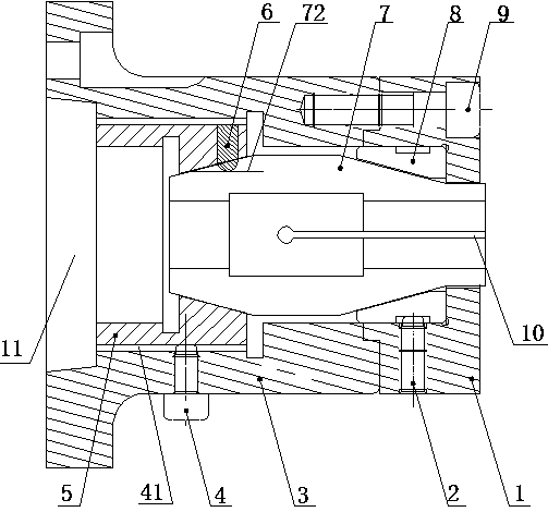
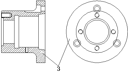
[0021] Such as Figure 1~6 As shown, the present invention is mainly composed of end cap 1, adjusting screw 2, base 3, positioning screw 4, front cone ring 8, rear cone ring 5, positioning pin 6, chuck body 7, connecting screw 9 and positioning pin 6. Such as Figure 7 As shown, this lathe chuck is mainly used for fixing the upper shaft 14 when turning the lower shaft 13 of the crankshaft 12. Since the crankshaft 12 of the body includes special structures such as eccentric wheels, which require high concentricity of the shaft, it is difficult for ordinary lathe chucks to Guaranteed concentricity, this lathe chuck sol...


PUM


Abstract

The invention discloses a lathe chuck, and belongs to the field of lathe work of crankshafts for air conditioner compressors. The lathe chuck comprises an adjusting screw, a connecting screw, a positioning screw and a positioning pin, and further comprises an end cover, a base, a front conical ring, a rear conical ring, an adjusting groove, a sliding groove and a chuck body, wherein the rear conical ring is arranged on a bevel at one end of the chuck body in a sleeved mode, the positioning pin is inserted in the adjusting groove in the chuck body after penetrating through the rear conical ring, the front conical ring is arranged on a bevel on the neck portion of the other end of the chuck body in a sleeved mode, the chuck body is placed in the base, the center line of the chuck body coincides with the center line of the base, the end cover is matched with the base and is connected with the base through the connecting screw, the adjusting screw is arranged at the bottom of the end cover, one end of the adjusting screw abuts against the front conical ring, the positioning screw is arranged at the bottom of the base, and the positioning screw penetrates through the base and is inserted in the sliding groove in the rear conical ring. The lathe chuck is used for clamping the shafts to be turned; because the front conical ring, the rear conical ring and the chuck body are combined, concentricity between the chuck and a lathe spindle can be conveniently adjusted, and product concentricity is stable.

Description

technical field [0001] The invention relates to the field of turning processing of crankshafts used in air-conditioning compressors. Specifically, the invention relates to a lathe chuck, which is used to clamp the crankshaft for turning. Background technique [0002] High concentricity is required in the process of shaft processing, especially the shaft-to-shaft concentricity used in precision instruments is now higher. The existing processing technology is to directly clamp the shaft to be turned on the chuck of the lathe chuck. On the jaws, if one jaw needs to be adjusted during processing, the other jaws will also move accordingly, making it difficult to adjust the coaxiality between the center line of the chuck and the spindle of the lathe. When the lathe rotates at high speed, only the axis of the chuck and the shaft If the axes are not on the same line, the concentricity of the product will be unstable and the accuracy will not be high, and the outer surface of the sha...

Claims


Application Information

Patent Timeline
Patent Type & Authority Applications(China)
IPC IPC(8): B23Q3/12
CPCB23Q3/12B23Q2703/105
Inventor 何春友于建芝饶家元
Owner WUHU YONGWEI REFRIGERATION ACCESSORIES MFG CO LTD
Learn More