Unmanned vehicle brake system for achieving double-loop brake

An unmanned vehicle and braking system technology, applied in the field of vehicle design, can solve the problems of low control precision, long transmission line of the braking system, and inability to fully reflect the precise control of the electronic control system, and achieve simple electronic control logic , The installation layout is easy to achieve

Inactive Publication Date: 2014-12-10
BEIJING INSTITUTE OF TECHNOLOGYGY
View PDF8 Cites 9 Cited by
  • Summary
  • Abstract
  • Description
  • Claims
  • Application Information

AI Technical Summary

Problems solved by technology

[0004] (1) The electric control brake modification at the brake pedal and the manual brake use the same actuator, which may cause interference between the two actions;
[0005] (2) The control accuracy of the motor pulling the cable to drive the brake pedal movement is not high, which is not conducive to the further research of the longitudinal control algorithm;
[0006] (3) When the brake system is depressurized, the brake pedal needs to overcome the resistance of the motor to return. When the brake pedal moves repeatedly, the point of the brake pedal’s return cannot be guaranteed to remain unchanged each time, and calibration is difficult;
[0007] (4) The transmission route of the brake system is long, which cannot fully reflect the characteristics of "fast response and precise control" of the electronic control system

Method used


Image

  • Unmanned vehicle brake system for achieving double-loop brake
  • Unmanned vehicle brake system for achieving double-loop brake

Examples


example 1

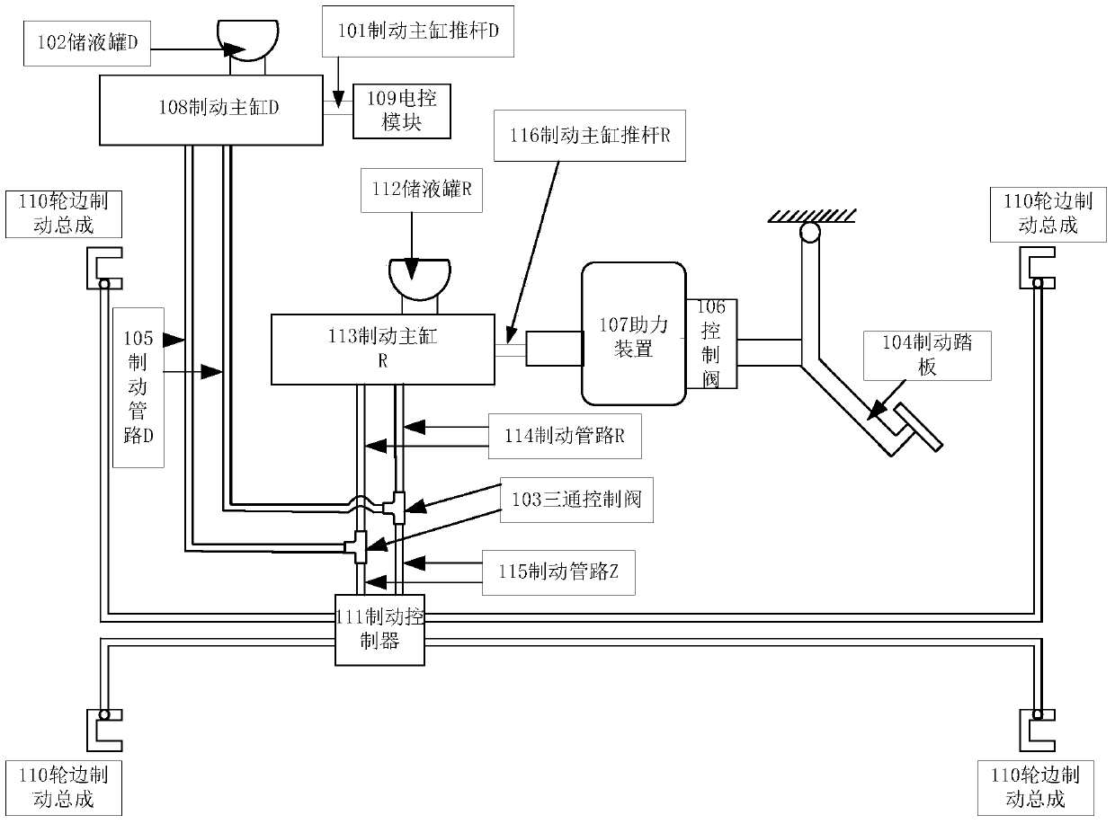
[0031] Such as figure 1 As shown, the present invention is a braking system for an unmanned vehicle for realizing dual-circuit braking. The system is mainly composed of a manual braking circuit, an electric braking circuit, a three-way control valve 103 and a braking pipeline Z115 composition; of which

[0032] The manual braking circuit includes a brake pedal 104, a control valve 106, a booster device 107, a brake master cylinder R113, a brake master cylinder push rod R116, a liquid storage tank R112 and a brake pipeline R114; the connection relationship is: The moving pedal 104 is connected to the booster device 107 through the control valve 106, the booster device 107 is connected to the control end of the brake master cylinder R113 through the brake master cylinder push rod R116, and the oil inlet of the brake master cylinder R113 is connected to the liquid storage tank R112 , the oil outlet of the brake master cylinder R113 is connected with the brake pipeline R114.

[...

example 2

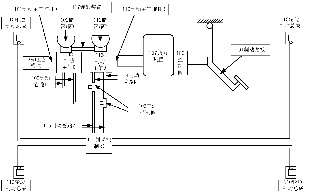
[0042] Such as figure 2 As shown, the present invention is a braking system for an unmanned vehicle for realizing dual-circuit braking. The system is mainly composed of a manual braking circuit, an electric braking circuit, a three-way control valve 103, and a braking pipeline Z115 and connecting device 117; where

[0043] The manual braking circuit includes a brake pedal 104, a control valve 106, a booster device 107, a brake master cylinder R113, a brake master cylinder push rod R116, a liquid storage tank R112 and a brake pipeline R114; the connection relationship is: The moving pedal 104 is connected to the booster device 107 through the control valve 106, the booster device 107 is connected to the control end of the brake master cylinder R113 through the brake master cylinder push rod R116, and the oil inlet of the brake master cylinder R113 is connected to the liquid storage tank R112 , the oil outlet of the brake master cylinder R113 is connected with the brake pipeli...


PUM


Abstract

The invention provides an unmanned vehicle brake system for achieving double-loop brake. The unmanned vehicle brake system is mainly composed of a manual brake loop, an electric brake loop, a three-way control valve and a brake pipeline Z. A brake pedal on the manual brake loop is connected with an assistance device through a control valve. The assistance device is connected with the control end of a main brake cylinder R through a main brake cylinder pushing rod R. An oil inlet of the main brake cylinder R is connected with a liquid storage tank R. An oil outlet of the main brake cylinder R is connected with a brake pipeline R. An electric control module on the electric brake loop is connected with the control end of a main brake cylinder D through a main brake cylinder pushing rod D. An oil inlet of the main brake cylinder D is connected with a liquid storage tank D. An oil outlet of the main brake cylinder D is connected with a brake pipeline D. The brake pipeline R and the brake pipeline D are connected with a three-way control valve. An oil outlet of the three-way control valve is connected with a brake controller through the brake pipeline Z. The brake controller is connected with a wheel side brake assembly of a vehicle.

Description

technical field [0001] The invention relates to a braking system for an unmanned vehicle for realizing dual-circuit braking, and belongs to the technical field of vehicle design. Background technique [0002] Unmanned vehicle challenges have been held at home and abroad, such as the Urban Challenge (Urban Challenge) held by DARPA (U.S. Defense Advanced Research Projects Agency) and the "Smart Vehicle Future Challenge" held by China. They are all researching unmanned vehicles, such as Mercedes-Benz S500 INTELLIGENT DRIVE, Google's unmanned vehicles, Nissan's electric self-driving vehicles, etc. However, in the research of unmanned vehicle technology at home and abroad, most of them are modified by adding external mechanisms to traditional vehicles. This method applies the instructions of the upper decision-making system to the external organization, which will lead to the incompatibility between the additional control system and the original control system of the car, making ...

Claims


Application Information

Patent Timeline
Patent Type & Authority Applications(China)
IPC IPC(8): B60T13/58
Inventor 陈慧岩张瑞琳李勇
Owner BEIJING INSTITUTE OF TECHNOLOGYGY
Why Eureka
Try Eureka