Tidal-flat ship
A tidal flat and ship hull technology, applied in ship construction, ship propulsion, ship parts, etc., can solve the problems of labor-intensive, easy to fall into the tidal flat, and its own weight is large, so as to reduce the contact area, reduce friction, and drive simple, convenient and fast. Effect
- Summary
- Abstract
- Description
- Claims
- Application Information
AI Technical Summary
Problems solved by technology
Method used
Image

Examples
Embodiment Construction
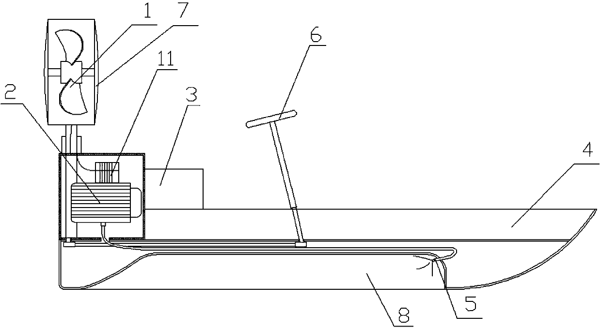
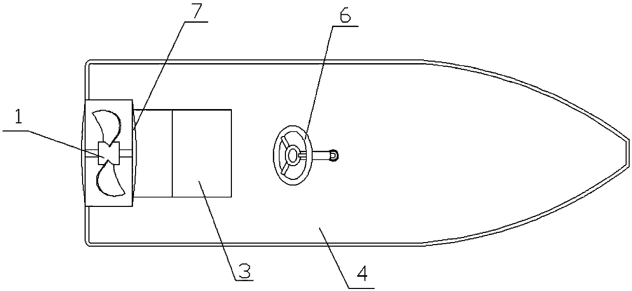
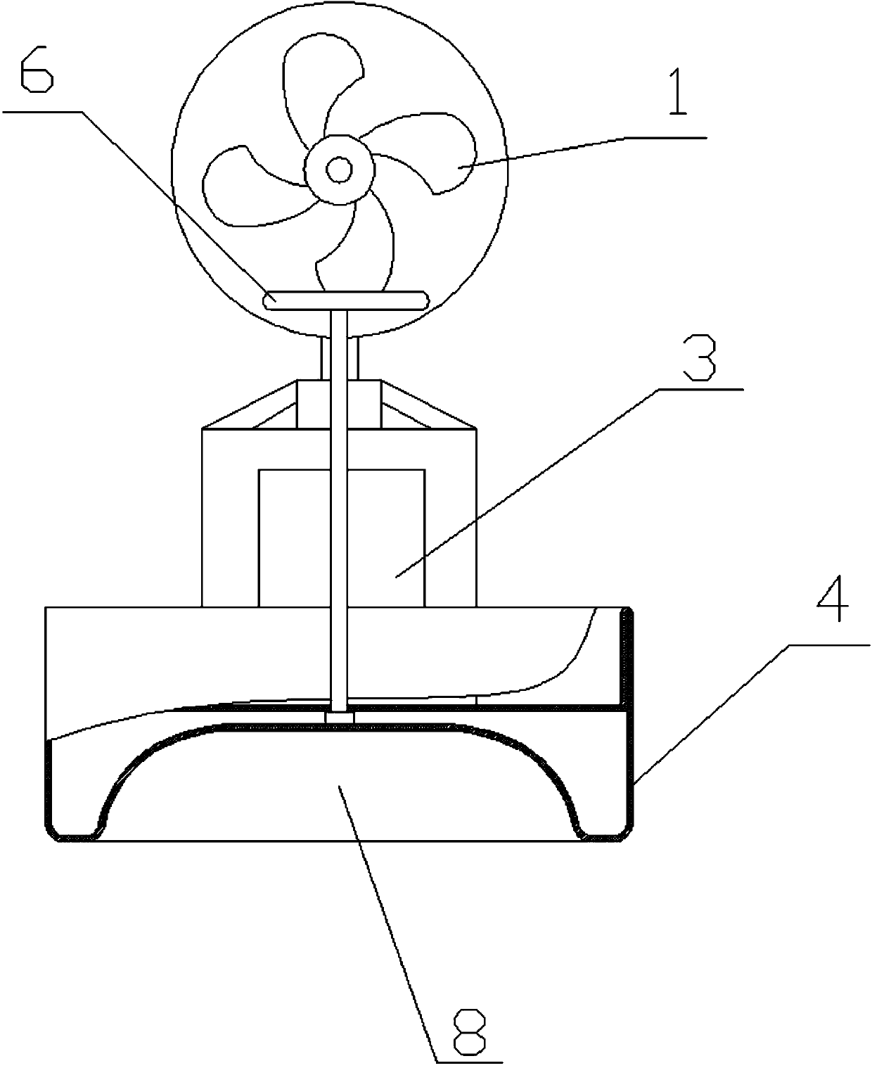
[0012] The following combination Figure 1 to Figure 3 As shown, the above and other technical features and advantages of the present invention are described in more detail.
[0013] It should be emphasized that the application of the present invention is not limited to a specific field, and only corresponds to a space capable of accommodating objects, regardless of the objects contained therein.
[0014] A tidal flat boat, comprising a hull 4 and a propulsion device and a steering device arranged on the hull 4, the steering device is connected to the propulsion device, the hull 4 also includes a floating device, and the bottom of the hull 4 is provided with Seal the cavity 8, the buoyant device is connected between the propulsion device and the sealed cavity 8, and the buoyant device injects compressed medium into the sealed cavity 8 to support the hull 4.
[0015] By adopting the above-mentioned technical scheme, both the propulsion device and the steering device are instal...
PUM
 Abstract
Description
Claims
Application Information
PatSnap Eureka turns technology decisions into work you can execute. Powered by our Innovation Knowledge Graph, it runs expert workflows across engineering, life sciences, materials and intellectual property. Get your review-ready output in minutes.


