Head belt unfolding device with belt sway switches

A technology of deviation switch and display belt, which is applied in the direction of conveyor control device, transportation and packaging, conveyor objects, etc., can solve the problems of inability to open, inaccessible, incapable of alarm and parking, and achieve the effect of preventing vicious accidents

Active Publication Date: 2014-12-10
SICHUAN ZIGONG CONVEYING MACHINE GRP
View PDF5 Cites 6 Cited by
  • Summary
  • Abstract
  • Description
  • Claims
  • Application Information

AI Technical Summary

Problems solved by technology

[0006] The purpose of the present invention is to provide a belt unwinding device with a deviation switch head, which solves the problem that the pressure roller set installed on the existing conveyor is severely twisted in the forming section of the conveyor belt, and cannot be opened, and the material is wrapped in a flat tube shape. The head roller, at this time, the two sides of the tape cannot touch the stop roller of the deviation switch, and the technical problems of alarm and parking cannot be achieved, so that the above-mentioned problems in the prior art can be effectively solved

Method used


Image

  • Head belt unfolding device with belt sway switches
  • Head belt unfolding device with belt sway switches

Examples


Embodiment 1

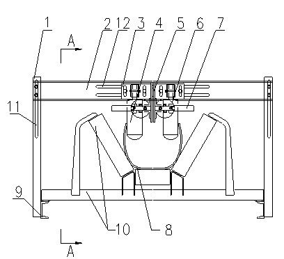
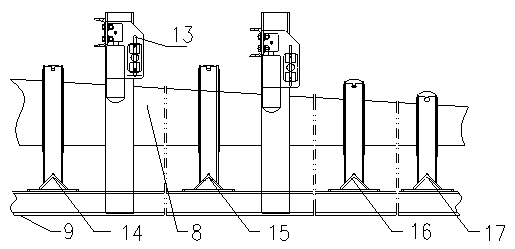
[0027] Example 1: The vertical height or horizontal width can be adjusted through the combination of long holes and bolts to ensure that all parts are in the best position when in use, so that the unwinding roller group is close to the conveyor belt. When the conveyor belt deviates, the conveyor belt will The side will touch the stop roller of the deviation switch, and push the stop roller to rotate, and send out an alarm and stop signal.

[0028] No. 1 long hole 11 is established on the upper end of pole 1, and the end of door beam 2 passes through No. 1 long hole 11 by bolt and is fixed, and the height of door beam 2 is adjusted by the position of bolt and No. 1 long hole 11. The No. 1 long hole on the poles on both sides is connected with the door beam. According to the different belt surface heights of the conveyor belt at different groove angles, adjust the height of the unwinding roller and the deviation switch to ensure that the unwinding roller can be inserted into th...


PUM


Abstract

The invention discloses a head belt unfolding device with belt sway switches. The head belt unfolding device with the belt sway switches comprises vertical rods, a transverse door beam, a belt unfolding roller base, belt unfolding rollers, a belt sway switch installation plate, the belt sway switches and a stop roller. Each end of the door beam is connected with the upper end of the corresponding vertical rod. The height of the door beam can be adjusted in the mode that the door beam is moved vertically at the connection positions. The upper end of the belt unfolding roller base is connected with the door beam. The belt unfolding roller base can be transversely moved at the connection position, so that the left position and the right position of the belt unfolding roller base can be adjusted. The belt unfolding rollers are located at the lower end of the belt unfolding roller base. The upper end of the belt sway switch installation plate is connected with the door beam. The belt sway switch installation plate can be transversely moved at the connection position so that the left position and the right position of the belt sway switch installation plate can be adjusted. The stop roller is connected with the lower end of the belt sway switch installation plate. The stop roller can be transversely moved at the connection position so that the left position and the right position of the stop roller can be adjusted. The belt sway switches are arranged on the stop roller. The stop roller can rotate with the belt sway switches as the center. By the adoption of the head belt unfolding device with the belt sway switches, a tubular conveyer belt can be forcibly unfolded, the belt sway switches are triggered to send out an alarming signal and a stop signal according to the deflection quantity, and fatal accidents are avoided.

Description

technical field [0001] The invention relates to a head belt spreading device with a deviation switch, in particular to a belt spreading device with a deviation switch head suitable for a tubular belt conveyor, which belongs to the technical field of tubular belt conveyors. [0002] Background technique [0003] Belt conveyor is an important bulk material conveying equipment, suitable for conveying powdery and small granular materials, such as ore, coal, gravel, sand, cement, fertilizer and grain, etc., widely used in metallurgy, mines, docks, Coal, electricity, cement, chemical and other industries. [0004] In the expansion section of the head of the traditional tubular belt conveyor, usually after the tubular conveyor belt becomes a 45° trough, belt rollers are set on both sides to forcibly expand the conveyor belt, and a deviation switch is set near the head. Alarm or stop immediately when the conveyor belt deviates. When the tubular conveyor belt twists slightly in th...

Claims


Application Information

Patent Timeline
IPC IPC(8): B65G39/10B65G43/02
Inventor 龚欣荣
Owner SICHUAN ZIGONG CONVEYING MACHINE GRP
Why Eureka
Try Eureka