Submerged membrane separation device and its operating method

A submerged, separation membrane technology, applied in the direction of semi-permeable membrane separation, chemical instruments and methods, membrane technology, etc., to achieve the effect of reducing operating power consumption and controlling membrane pollution

Inactive Publication Date: 2017-01-04
天津海龙津阳材料科技有限公司
View PDF8 Cites 0 Cited by
  • Summary
  • Abstract
  • Description
  • Claims
  • Application Information

AI Technical Summary

Problems solved by technology

[0004] The purpose of the present invention is to provide a submerged membrane separation device and its operating method for the deficiencies of the membrane pollution control technology in the operation process of the existing submerged membrane separation device. The membrane separation device and its membrane pollution control method can realize membrane pollution. Low-cost and stable operation of the separation device

Method used


Image

  • Submerged membrane separation device and its operating method
  • Submerged membrane separation device and its operating method

Examples


Embodiment 1

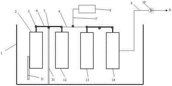
[0019] Embodiment one, such as figure 1 Shown:

[0020] Membrane units 2, 12, 13, 14 are respectively arranged on the positioning guide rails 11 perpendicular to the liquid surface of the water tank, and immersed in the water tank 1. The two cantilever ends of the balance bar 4 are connected to the membrane unit through the rotatable connector 3. 2 and the membrane unit 12 are connected to form a balance group, and 5 is the gravity balance fulcrum of the balance bar; the same balance bar is used to connect the membrane unit 13 and the membrane unit 14 to form another balance group; the two balance groups pass through the linkage rod 6 and the traction Steel rope 7 and traction motor 8 form a linkage group. The balance bar 4 or the linkage bar 6 is connected with the support 31 vertically erected and fixed in the water tank through the gravity balance fulcrum 5 .

[0021] The produced water is pumped out by the produced water pump 10 through the produced water pipe 9 . The s...

Embodiment 2

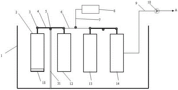
[0024] Embodiment two, such as figure 2 Shown:

[0025] The bottom ends 18 of the membrane units 2, 12, 13, 14 are fixed on the bottom of the water tank 1, and the upper sides of the membrane units 2, 12, 13, 14 are respectively slidably positioned on the positioning guide rails vertically erected in the water tank. The upper part is pulled and lifted by the traction motor, and other operating modes are the same as in Embodiment 1, such as figure 1 shown. In this way, as the upper end of the hollow fiber membranes in the membrane units 2, 12, 13, 14 is pulled up and down by the traction motor, the membranes change periodically from nearly stretching to bending, and the hollow fiber membranes can also be bent. Mechanical scour occurs between the filament and the water body, thereby preventing the accumulation of pollutants on the surface of the hollow fiber membrane and between the filaments of the hollow fiber membrane.

[0026] The content not described in the embodiment ...


PUM


Abstract

The invention provides a submerged membrane separation device and its operation method. The device includes a water tank, a product water extraction pump and several membrane units; several membrane units are respectively immersed in the water tank, and the product water extraction pump and the water tank pass through the water production pipe. Connection; the improvement is: cancel the high-energy blower configuration, and set up a traction motor instead, the membrane unit frames are connected by a balance bar, and the traction motor is connected with the balance bar connecting the membrane unit frame through a traction component; its operation method It is: first start the traction motor; then through the mechanical traction of the traction motor, the whole of several membrane units located in the tank moves up and down periodically or only the upper end of the membrane unit moves up and down periodically; the hollow fiber membrane of the membrane unit moves up and down periodically. There is a mechanical scour effect with the water body, thereby preventing the accumulation of pollutants on the surface of the hollow fiber membrane and between the hollow fiber membrane filaments; the power of the traction motor is small, which can realize the low-cost and stable operation of the membrane reactor.

Description

technical field [0001] The invention relates to a submerged membrane separation device used for membrane pollution control in the membrane separation process and an operation method thereof. Background technique [0002] Membrane bioreactor is the product of the combination of traditional activated sludge method and emerging membrane separation technology. It uses membrane separation components to replace the secondary settling tank in the traditional process, which can not only greatly reduce the floor area, but also significantly improve the solid The efficiency of liquid separation has significantly improved the quality of effluent. Membrane chemical reactor is the integration of chemical reaction process and membrane separation process, such as the integration of chemical flocculation and membrane separation process in the tap water purification process, or the integration of biological fermentation reaction and membrane separation process, etc. As the membrane separati...

Claims


Application Information

Patent Timeline
Patent Type & Authority Patents(China)
IPC IPC(8): C02F3/12B01D65/08
Inventor 吕晓龙
Owner 天津海龙津阳材料科技有限公司
Why Eureka
Try Eureka