A tool for filling liquid electrolyte in an electrolyzer

A liquid electrolyte and electrolytic cell technology, which is applied in the field of aluminum smelting, can solve the problems of reducing insulation level and insulation pouring damage, and achieve the effects of avoiding burning damage, ensuring safety, and reducing splash loss.

Inactive Publication Date: 2016-07-06
ZHENGZHOU FAXIANG ALUMINUM IND
View PDF2 Cites 0 Cited by
  • Summary
  • Abstract
  • Description
  • Claims
  • Application Information

AI Technical Summary

Problems solved by technology

The gantry pillars of the electrolytic cell and the insulation between the pillars and the tank shell will be damaged by the splashed liquid electrolyte, which reduces the insulation level.

Method used


Image

  • A tool for filling liquid electrolyte in an electrolyzer
  • A tool for filling liquid electrolyte in an electrolyzer
  • A tool for filling liquid electrolyte in an electrolyzer

Examples


Embodiment Construction

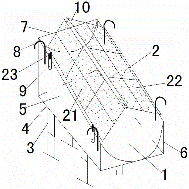
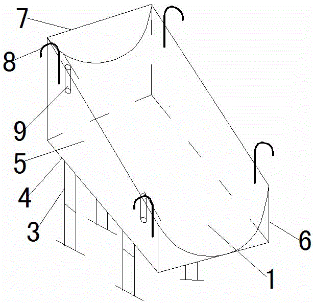
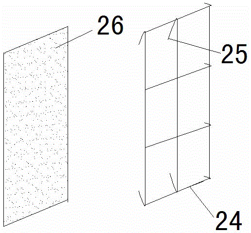
[0014] Such as figure 1 , 2 , 3 and 4, a tool for pouring liquid electrolyte into an electrolytic cell, including a chute and a chute cover 2 covering the top of the chute. The chute includes a chute shell and a chute 1. The bottom plate 4 with the bracket 3, the left side baffle 5, the right side baffle 6 and the rear side baffle 7 are constituted. The trough shell is provided with a slide pipe 1 along the axis direction of the bottom plate 4, the left side baffle 5 and the right side The front and rear ends of the plate 6 are provided with a pair of hooks 8 respectively. The left baffle 5 between the two hooks 8 is provided with a vertical pipe 9 at intervals. The chute cover 2 consists of a left cover 21 and a right The side cover 22 is composed of the left cover 21 and the right cover 22 connected by a connecting tube 10 and arranged symmetrically with respect to the connecting tube 10, and a 60° clamp is formed between the left cover 21 and the right cover 22 At the corner...


PUM

PropertyMeasurementUnit
angleaaaaaaaaaa

Abstract

A tool for filling liquid electrolyte in an electrolytic tank, including a chute and a chute cover covering the top of the chute. The baffle plate and the rear side baffle plate are composed of a slide pipe along the axis of the bottom plate in the tank shell. A pair of hooks are respectively provided at the front and rear ends of the left and right baffle plates. The left side baffle plate between the two hooks There are vertical pipes at intervals on the board. The chute cover is composed of left and right cover plates. The two cover plates are connected by a connecting pipe and arranged symmetrically relative to the connecting pipe. The two cover plates form an included angle, 60°≤the The included angle is less than or equal to 150°. There are vertical support rods at intervals on the left side of the left cover plate. The distance between the two support rods is equal to the distance between the two pipes. The two support rods are located in the two pipes. Advantages: It reduces the splash loss of liquid electrolyte, avoids the burning of the gantry column and insulating plate of the electrolyzer, and ensures the safety of the personnel involved in the start-up of the electrolyzer on site.

Description

Technical field [0001] The invention belongs to the technical field of aluminum smelting, and specifically relates to a tool for pouring liquid electrolyte into an electrolytic cell. Background technique [0002] The initial stage of normal production of the aluminum electrolysis cell is the construction of the aluminum electrolysis cell and the installation of the upper portion of the electrolysis cell. After the installation work is accepted, it will be handed over to the electrolysis worker for the installation of the furnace. After 72 hours of baking, the temperature of the electrolysis cell is close to or reaches the start of the electrolysis cell. Then, the pre-baked electrolyte from other normal production electrolyzers is drawn out using a vacuum table bag, and poured into the electrolyzer to be started. After the electrolyte is poured in, the voltage of the electrolytic cell is pulled to above 8V, the start-up of the electrolytic cell is finished, and then the next step ...

Claims


Application Information

Patent Timeline
Patent Type & Authority Patents(China)
IPC IPC(8): C25C3/14
Inventor 刘俊森刘驰吴中华
Owner ZHENGZHOU FAXIANG ALUMINUM IND
Why Eureka
Try Eureka