Hybrid Drive Unit and Drive Train for Motor Vehicle

A technology of hybrid power and drive unit, applied in the field of power transmission system, can solve the problems of contact between oil and torque converter, slow down of oil flow, etc., and achieve the effect of improving cooling, efficient cooling and avoiding clogging

Pending Publication Date: 2021-02-26
ZF FIEDRICHSHAFEN AG
View PDF2 Cites 0 Cited by
  • Summary
  • Abstract
  • Description
  • Claims
  • Application Information

AI Technical Summary

Problems solved by technology

[0006] However, this solution does not prevent oil from coming into contact with the torque converter when a motor vehicle with such a transmission assembly is descending a slope or during its severe braking
The baffles may even slow down the flow of oil after this working condition

Method used


Image

  • Hybrid Drive Unit and Drive Train for Motor Vehicle
  • Hybrid Drive Unit and Drive Train for Motor Vehicle
  • Hybrid Drive Unit and Drive Train for Motor Vehicle

Examples


Embodiment Construction

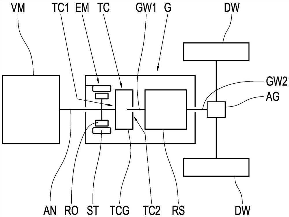
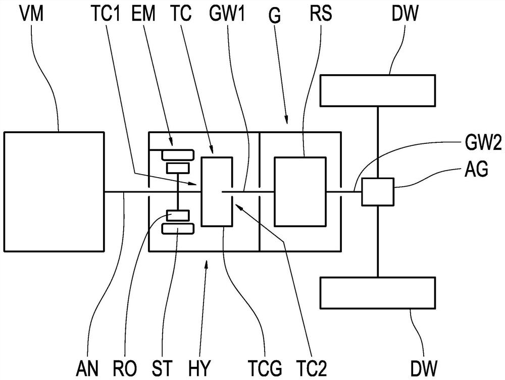
[0027] figure 1 A powertrain for a motor vehicle is schematically shown. The drive train has a combustion engine VM, the output of which is connected to the connection shaft AN of the transmission G. The transmission G forms the hybrid powertrain unit of the powertrain and has an electric machine EM with an anti-rotational stator ST and a rotatable rotor RO. The rotor RO is connected to the connecting shaft AN and to the housing TCG of the torque converter TC. The torque converter TC is connected on the output side to the input shaft GW1 of the transmission wheelset RS. The output shaft GW2 of the transmission wheelset RS is connected via the differential AG to the drive wheels DW of the motor vehicle. The torque converter housing TCG has a first end side TC1 and a second end side TC2 . The electric machine EM and the torque converter TC are arranged directly next to each other, whereby the electric machine EM is arranged directly on the first end side TC1 of the torque co...


PUM


Abstract

The invention relates to a hybrid drive unit (HY, G) for a motor vehicle, and the hybrid drive unit (HY, G) includes a housing (GG), in which a torque converter (TC) and an electric machine (EM) are accommodated. The electric machine (EM) and the torque converter (TC) are arranged directly next to each other such that the electric machine (EM) is arranged at a first face end (TC1) of the torque converter housing (TCG). An oil guide shell (LS) at least partially encompasses a section of the torque converter (TC). The oil guide shell (LS) has an L-shaped cross-section including a first section (LS1) and a second section (LS2) and is arranged in such that the first section (LS1) partially encompasses a second face end (TC2) of the torque converter housing (TCG) and the second section (LS2) partially encompasses a circumferential surface of the torque converter housing (TCG).

Description

technical field [0001] The invention relates to a hybrid drive unit for a motor vehicle and to a drive train for a motor vehicle having such a hybrid drive unit. Background technique [0002] The hybrid drive unit can be an integral part of a transmission which is adapted for establishing different transmission ratios between the combustion engine and the drive wheels of the motor vehicle. As an alternative thereto, the hybrid drive unit can be designed as a separate structural unit which is arranged in the drive train between the combustion engine and the transmission. Such structural units are also referred to as hybrid modules. [0003] For example, patent application DE 10 2014 118 485 A1 describes a mechanism for such a hybrid drive unit. The mechanism includes a front module with an electric machine and a loose clutch, a transmission behind the front module, a torque converter between the front module and the transmission, and a guide radially between the torque conv...

Claims


Application Information

Patent Timeline
Patent Type & Authority Applications(China)
IPC IPC(8): B60K6/40B60K6/42B60K6/38F16H57/04
CPCB60K6/40B60K6/42B60K6/38F16H57/0417F16H57/0435F16H57/0436H02K9/19H02K7/006H02K7/116F16H2200/201F16H2200/2041F16H57/0441F16H57/0453F16H57/0476F16H57/0443F16H57/0423F16H57/0409F16H57/0457B60K6/48B60K2006/4825B60K6/387B60K6/547B60K6/365Y02T10/62B60K6/405B60K6/26B60K6/36B60Y2200/92F16H57/02H02K7/10F16H2057/02043
Inventor T·贾玛蒂L·德伯尼茨T·穆勒S·斯特罗夫A·古彻P·莱因德斯T·拉茨曼
Owner ZF FIEDRICHSHAFEN AG
Why Eureka
Try Eureka