Continuous-spinning assembly and disassembly frame and torque and rotation speed control method

A technology of speed control and disassembly rack, applied in earth-moving drilling, drilling equipment, drill pipe, etc., can solve problems such as low work efficiency, exit from the market, and excessive torque, so as to improve work efficiency and achieve relatively accurate torque control. Effect

Active Publication Date: 2014-12-10
DEZHOU UNITED GASOLINEEUM MACHINERY
View PDF9 Cites 8 Cited by
  • Summary
  • Abstract
  • Description
  • Claims
  • Application Information

AI Technical Summary

Problems solved by technology

[0002] At present, two types of turnbuckle equipment are mainly used in the market to disassemble and assemble the threaded connection of oil pipes. One is a hydraulic disassembly stand. Repeated clamping and buckling has the disadvantages of low work efficiency and severe bites on the surface of the pipe. At present, this kind of disassembly frame is gradually withdrawing from the market.
[0003] The other is a continuous rotation high-torque screwing machine, such as Chinese patent documents CN2898265Y, CN201934039U, CN203515391U, and CN203515394U. The working mode of this type of screwing equipment is that the hydraulic clamp is driven by a high-torque deceleration motor to continuously rotate, and the screwing machine needs to take into account The function of make-up and breakout, and the general breakout torque is about 2 to 3 times the rated make-up torque, the design torque of this kind of high-torque screwing machine is generally more than 3 times the rated make-up torque, there is a The overall structure of the equipment is huge, the cost is high, and the energy consumption is high.
[0004] Although some of these two turnbuckle devices are equipped with a torque display module, which can display the torque value in real time, the control of the final make-up torque of the pipe is still controlled by humans, and there are potential safety hazards caused by human factors that cause the torque to exceed the standard.

Method used


Image

  • Continuous-spinning assembly and disassembly frame and torque and rotation speed control method
  • Continuous-spinning assembly and disassembly frame and torque and rotation speed control method
  • Continuous-spinning assembly and disassembly frame and torque and rotation speed control method

Examples


Embodiment Construction

[0039] The present invention is described below with a specific embodiment as an example:

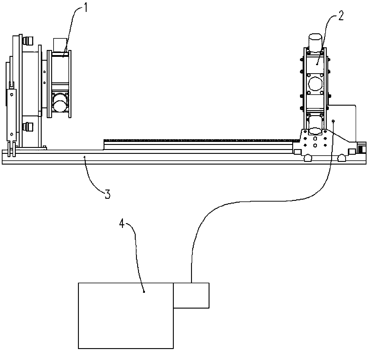
[0040] Refer to the attached figure 1 , for the current disassembly rack with continuous turn buckle function, its basic structure usually includes the following basic components:

[0041] The first is a base 3 which serves as a base for the rest of the installation, usually in a certain orientation, such as figure 1 There is a section of track in the left and right direction shown in , which is the basis of the pincer structure, used to clamp the pipe body, so as to perform continuous rotation.

[0042] Configured as a jaw, two parts are required, one part is the mobile back tong 2, the movement is reflected in the movement on the track, thus, the movement of the mobile back tong 2 is controllable, and it is locked after moving in place. Of course, the lock Tightness can also be expressed as a continuous force component, which is used to provide continuous clamping force.

[0043] T...


PUM


Abstract

The invention discloses a continuous-spinning assembly and disassembly frame and a torque and rotation speed control method. Through torque control, the requirements for torque of spinning at different stages are met, breakout is configured through separation and reunion, therefore, during continuous spinning and reciprocating punching, a workpiece does not need to be clamped repeatedly and makeup and breakout can be completed through one-time clamping. For most driving devices, due to the fact that the output power is fixed, when the speed is high, output torque is reduced correspondingly, therefore, the spinning speed can be automatically switched according to spinning torque by using the characteristic, the smaller the torque is, the higher the rotation speed is, and the working efficiency is effectively improved; when a set torque value is reached, unloading can be conducted automatically, and relatively accurate control over the torque is realized.

Description

technical field [0001] The invention belongs to the technical field of petroleum machinery, and relates to a continuous turn-buckle dismounting frame for oil pipes and a torque speed control method using the continuous turn-buckle disassembly frame. Background technique [0002] At present, two types of turnbuckle equipment are mainly used in the market to disassemble and assemble the threaded connection of oil pipes. One is a hydraulic disassembly stand. Repeated clamping and buckling has the disadvantages of low work efficiency and serious damage to the surface of the pipe. At present, this disassembly frame is gradually withdrawing from the market. [0003] The other is a continuous rotation high-torque screwing machine, such as Chinese patent documents CN2898265Y, CN201934039U, CN203515391U, and CN203515394U. The working mode of this type of screwing equipment is that the hydraulic clamp is driven by a high-torque deceleration motor to continuously rotate, and the screwi...

Claims


Application Information

Patent Timeline
IPC IPC(8): E21B19/16
Inventor 张桂昌宫兆玲孙伟庞文焕王宗雷刘永
Owner DEZHOU UNITED GASOLINEEUM MACHINERY
Why Eureka
Try Eureka