
Distributed fiber-optic sensing based oil-gas pipeline safety monitoring system and method

A distributed optical fiber and safety monitoring technology, which is applied in the pipeline system, gas/liquid distribution and storage, mechanical equipment, etc., can solve the problems of increased cost, high cost, and reduced system sensitivity, achieving low insertion loss and avoiding hardware devices , the effect of good application prospects

Active Publication Date: 2014-12-10
SUZHOU GUANGLAN INFORMATION TECH
View PDF5 Cites 10 Cited by
  • Summary
  • Abstract
  • Description
  • Claims
  • Application Information

AI Technical Summary

Problems solved by technology

[0005] Due to some inherent limitations of their respective technical theories, taking the Mach-Zehnder interferometric positioning technology and the notch point positioning technology of the optical fiber white light interferometer as examples, the Mach-Zehnder interferometric positioning technology must use a high-speed synchronous acquisition device, which is costly and expensive. As the monitoring distance increases to a certain distance, the cost increases sharply; and the notch point positioning technology of the optical fiber white light interferometer has a delay fiber ring, and the delay fiber ring itself will also produce a notch point, which is easy to cause in the long-distance positioning process. Notch point aliasing interference phenomenon, and reducing the delay fiber ring length to solve the aliasing problem will reduce the sensitivity of the system
[0006] The above various technologies have not been able to improve the pipeline security to a good application level, and there is still a lack of effective pipeline security technology products in the market. In view of the above problems, a simple and low-cost optical fiber positioning type transmission Oil and gas pipeline safety monitoring method is imperative

Method used


Image

  • Distributed fiber-optic sensing based oil-gas pipeline safety monitoring system and method
  • Distributed fiber-optic sensing based oil-gas pipeline safety monitoring system and method
  • Distributed fiber-optic sensing based oil-gas pipeline safety monitoring system and method

Examples


Embodiment Construction

[0037] The present invention will be further described below in conjunction with the accompanying drawings. The following examples are only used to illustrate the technical solution of the present invention more clearly, but not to limit the protection scope of the present invention.

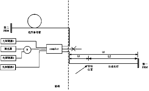
[0038] Such as figure 1 As shown, the oil and gas pipeline safety monitoring system based on distributed optical fiber sensing of the present invention includes a laser, a first photodetector (photodetector 1), a second photodetector (photodetector 2), a third photodetector Detector (photodetector 3), 3×3 fiber coupler (coupler), first sensing fiber terminal FRM (first FRM) and second sensing fiber terminal FRM (second FRM), laser, second light The detector is connected to the first input end of the 3×3 fiber optic coupler through the optical fiber circulator M, and the first optical detector and the third optical detector are respectively connected to the second and third input ends of the 3×3...


PUM


Abstract

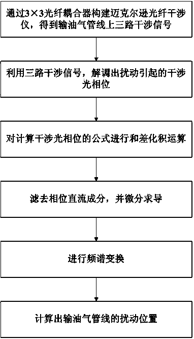
The invention discloses a distributed fiber-optic sensing based oil-gas pipeline safety monitoring system and method. The method includes the steps of 1, establishing a Michelson fiber-optic interferometer with a 3*3 fiber-optic coupler to obtain three interference signals of an oil-gas pipeline, with each two of the interference signals, having a fixed phase difference 2Pi / 3; 2, demodulating the interference signals to obtain an interference optical phase Delta Phi(5t) caused by disturbance; 3, subjecting a formula of the interference optical phase Delta Phi(5t) to a sum-difference to product operation; 4, filtering a phase direct-current component and performing derivation by differentiation; 5, performing spectrum transformation; 6, calculating a disturbance position L2 of the oil-gas pipeline. The distributed fiber-optic sensing based oil-gas pipeline safety monitoring system and method has the advantages that complex and expensive hardware equipment is omitted, the diploma of sensitivity and trapped wave point aliasing in the white light interferometer positioning technology is also avoided, insertion loss is low, the system and the method are applicable to safety warning for long-distance wide-range oil and gas pipelines, an available monitoring range is up to 150km, and the system and the method have a promising application prospect.

Description

technical field [0001] The invention relates to an oil and gas pipeline safety monitoring system and method based on distributed optical fiber sensing, and belongs to the technical field of oil and gas pipeline safety early warning. Background technique [0002] With the increasing development of my country's economy, pipeline safety, especially oil and gas pipelines, has been a subdivided area that has received important attention in recent years. If the oil and gas pipeline breaks and leaks, it will cause a huge impact on the lives of residents; if the oil and gas pipeline If it is damaged, it will bring huge potential safety hazards and cause immeasurable economic losses. [0003] As we all know, most of the alarm monitoring systems in the prior art are supported by multiple channels, and this kind of system needs to control the respective channels through the software of each different channel. Moreover, the cost of establishment and maintenance is relatively high, and i...

Claims


Application Information

Patent Timeline
IPC IPC(8): F17D5/02
Inventor 吴东方
Owner SUZHOU GUANGLAN INFORMATION TECH
Learn More