Air conditioner refrigeration device
A technology for air-conditioning refrigeration and equipment, applied in refrigerators, refrigeration components, refrigeration and liquefaction, etc., can solve the problems of adverse effects on cycle performance and large pressure drop of air-conditioning refrigeration equipment, achieve stable work, reduce cycle resistance, and improve heat exchange. performance effect
- Summary
- Abstract
- Description
- Claims
- Application Information
AI Technical Summary
Problems solved by technology
Method used
Image
Examples
Embodiment 1
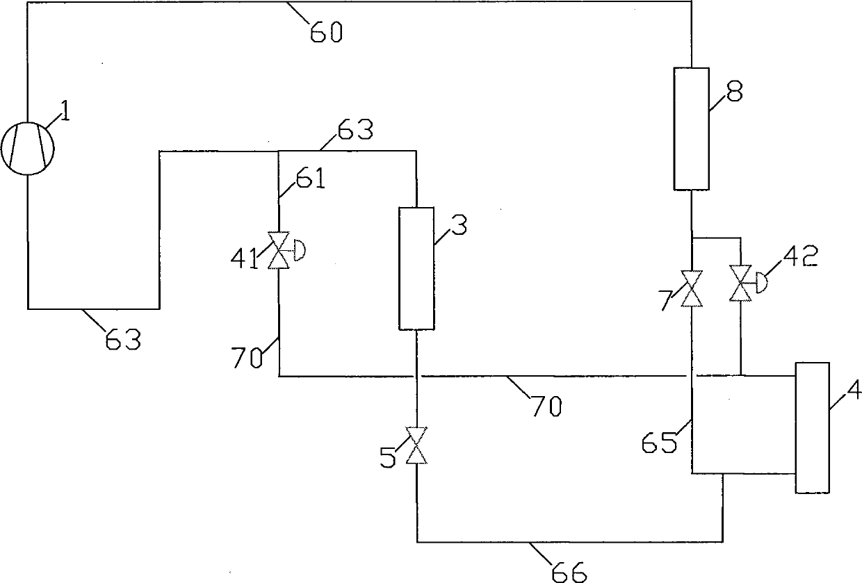
[0033] Such as figure 1 As shown, the entire air conditioning and refrigeration equipment includes the following components: compression mechanism 1, first throttling mechanism 5, second throttling mechanism 7, user-side heat exchanger 3, heat source side heat exchanger 4, heater 8, first The flow direction control valve 41 and the second flow direction control valve 42; the first throttling mechanism 5 and the second throttling mechanism 7 are electronic expansion valves; the first flow direction control valve 41 and the second flow direction control valve 42 are electromagnetic valves.
[0034] The connection method of each component of the above air-conditioning and refrigeration equipment is as follows:
[0035] The outlet end of the heater 8 passes through the second throttling mechanism 7 and the sixty-fifth pipe 65 sequentially, and is connected to any one of the two connection ports of the heat source side heat exchanger 4 , and the other connection port of the heat s...
Embodiment 2
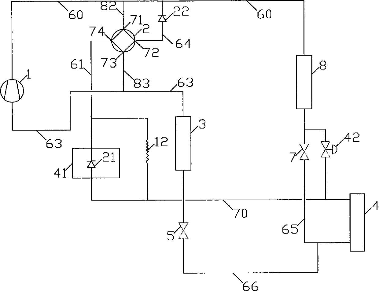
[0054] Such as figure 2 as shown, figure 2 The scheme shown is the same as figure 1 The difference in the scheme shown is: figure 1 Compared to the scheme shown, the figure 2 In the shown solution, a four-way valve 2, a second one-way valve 22 and a capillary 12 are added, and at the same time, the first one-way valve 21 is used instead figure 1 The first flow in the illustrated solution is directed to the control valve 41 .
[0055] figure 2 The connection methods of the various components of the air-conditioning and refrigeration equipment shown are as follows:
[0056] The outlet end of the heater 8 passes through the second throttling mechanism 7 and the sixty-fifth pipe 65 sequentially, and is connected to any one of the two connection ports of the heat source side heat exchanger 4 , and the other connection port of the heat source side heat exchanger 4 The connection port is connected to any one of the two connection terminals of the first flow direction con...
Embodiment 3
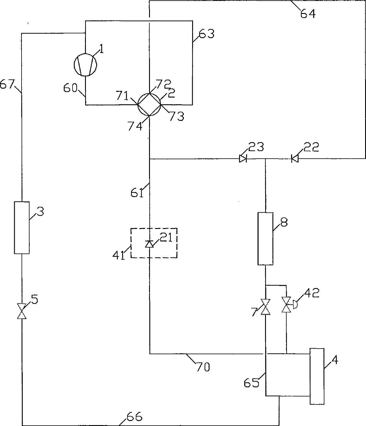
[0080] Such as image 3 As shown, the whole air-conditioning and refrigeration equipment except comprising embodiment 1 figure 1 In addition to all the components of the shown scheme, a four-way valve 2, a second one-way valve 22, and a third one-way valve 23 are added; in addition, a first one-way valve 21 can be used to replace the first one-way valve. One flow to the control valve 41.
[0081] image 3 The connection methods of the various components of the air-conditioning and refrigeration equipment shown are as follows:
[0082] The outlet end of the heater 8 passes through the second throttling mechanism 7 and the sixty-fifth pipe 65 sequentially, and is connected to any one of the two connection ports of the heat source side heat exchanger 4 , and the other connection port of the heat source side heat exchanger 4 The connection port is connected to any one of the two connection terminals of the first flow direction control valve 41 through the seventieth pipeline 7...
PUM
 Abstract
Description
Claims
Application Information
 - R&D
- Intellectual Property
- Life Sciences
- Materials
- Tech Scout
- Unparalleled Data Quality
- Higher Quality Content
- 60% Fewer Hallucinations
Browse by: Latest US Patents, China's latest patents, Technical Efficacy Thesaurus, Application Domain, Technology Topic, Popular Technical Reports.
© 2025 PatSnap. All rights reserved.Legal|Privacy policy|Modern Slavery Act Transparency Statement|Sitemap|About US| Contact US: help@patsnap.com


