Photoelectric correction sensor for variable semitransparent coiled material and detection method for same

A photoelectric deviation correction and photoelectric detection technology, which is applied in the direction of using optical devices, instruments, measuring devices, etc., can solve the problems of poor deviation correction effect of the measured strip

Inactive Publication Date: 2014-12-10
CHINA JILIANG UNIV
View PDF5 Cites 5 Cited by
  • Summary
  • Abstract
  • Description
  • Claims
  • Application Information

AI Technical Summary

Problems solved by technology

[0004] The purpose of the present invention is to solve the problem that the existing deviation correction detection system is susceptible to changes in the stretching state of the measured strip when performing deviation correction detection on the stretchable translucent measured strip, which affects the poor deviation correction effect of the measured strip Insufficient, provide a kind of photoelectric correction sensor and Its detection method

Method used


Image

  • Photoelectric correction sensor for variable semitransparent coiled material and detection method for same
  • Photoelectric correction sensor for variable semitransparent coiled material and detection method for same
  • Photoelectric correction sensor for variable semitransparent coiled material and detection method for same

Examples


example 1

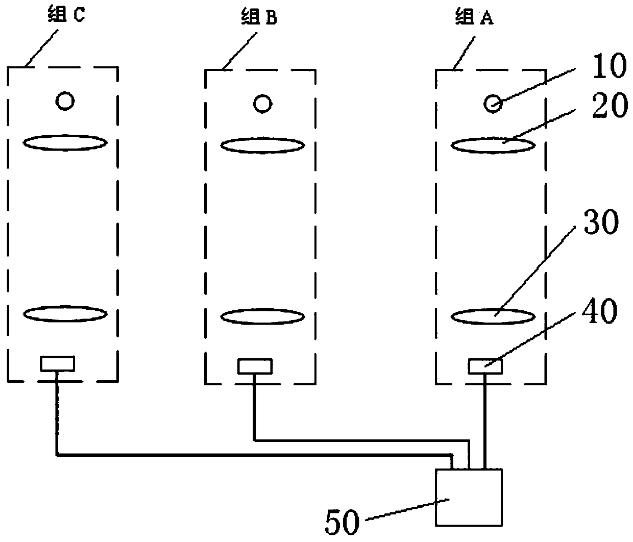
[0051] Example 1: A photoelectric correction sensor for variable translucent coils, see figure 1 , figure 2 As shown, it includes two brackets (the brackets are not shown in the description of the drawings), one of which is fixedly connected to the coiler near the front end of the longitudinal running section of the strip to be tested, and the other bracket is fixedly connected to the coiler near the front end of the strip to be tested. On the coiler above the rear end side of the longitudinal walking section of the material. And three groups of identical photoelectric detection units are arranged horizontally side by side on each bracket, and these three groups of identical photoelectric detection units are respectively marked as group A, group B and group C. Each group of photoelectric detection units includes a light source 10, a No. 1 collimator lens 20 that can generate parallel light, a No. 2 collimator lens 30 that can condense light, and a photosensitive device 40, a...

example 2

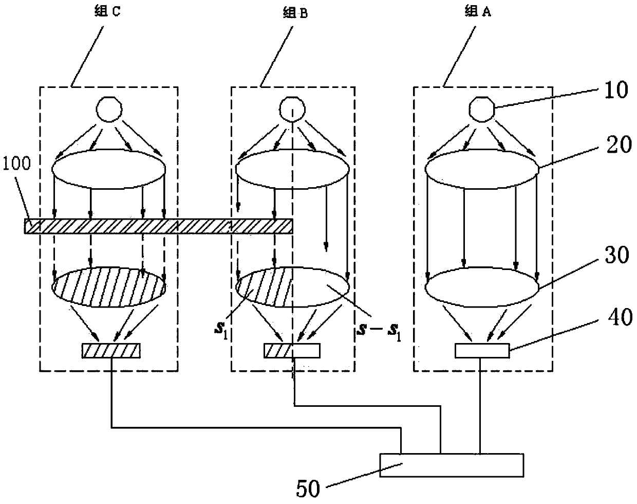
[0078] Example 2: A detection method of a photoelectric correction sensor for variable translucent coils, see figure 1 , figure 2 As shown, if in step 2 of Example 1, when laying out the strip to be tested on the coiler, the strip to be tested is arranged horizontally so that the center of the No. 1 collimator lens and the center of No. 2 collimator lens The center line of the test strip is perpendicular to the horizontal plane of the tested strip, and the side edge of the tested strip and the center line fall together in a vertical vertical plane, so that the No. 2 collimator lens of group B is tested Area S of tape shielding 1 is half of the light transmission area S of the No. 2 collimator lens of group B, that is

[0079] The detection method and working process of the photoelectric detection unit in the example two are the same as the example one, because the area S of the No. 2 collimator lens of group B is blocked by the strip material to be tested 1 is half of th...

example 3

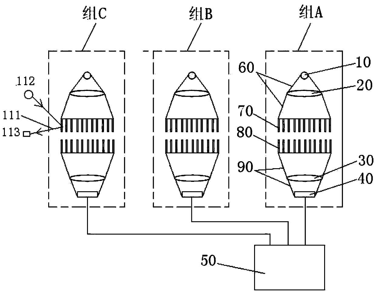
[0080] Example 3: A photoelectric correction sensor for variable translucent coils, see image 3 As shown, Example 3 is a schematic diagram of the structure and principle after adding the upper light-absorbing cover, the lower light-absorbing cover, the upper flexible light-absorbing curtain whiskers and the lower flexible light-absorbing curtain to the structural principle schematic diagram of Example 1. An upper light-absorbing sleeve 60 is tightly connected to the edge of the No. 1 collimator lens, and the upper end of the upper light-absorbing sleeve is tightly connected to the lamp holder of the light source. The opening diameter of the lower end of the upper light-absorbing sleeve is larger than the diameter of the No. 1 collimator lens. A plurality of upper flexible light-absorbing curtain whiskers 70 freely facing downwards are connected to the edge of the lower opening of the upper light-absorbing sleeve, and the length of each upper flexible light-absorbing curtain wh...


PUM


Abstract

The invention discloses a photoelectric correction sensor for a variable semitransparent coiled material and a detection method for the same, and belongs to the technical field of photoelectric correction detection. The photoelectric correction sensor and the detection method for the same are free from the influence of the stretching state of the detected coiled material during correction detection on the stretchable semitransparent detected coiled material. The photoelectric correction sensor comprises a support, wherein three groups of identical photoelectric detection units are arranged on the support, each group of the photoelectric detection units comprises a light source, a first collimation lens, a second collimation lens and a photosensitive device, the light source, the first collimation lens, the second collimation lens and the photosensitive device in the same group of the photoelectric detection units are sequentially arranged from top to bottom along a vertical straight line, the light source is arranged at the focus of the first collimation lens, the first collimation lens and the second collimation lens are oppositely arranged in parallel, and the photosensitive device is arranged at the focus of the second collimation lens; the voltage output end of each photosensitive device is in one-to-one connection with the three voltage output interfaces of the photoelectric correction sensor respectively.

Description

technical field [0001] The invention relates to the technical field of photoelectric deviation correction detection, in particular to a photoelectric deviation correction sensor for variable translucent coils and a detection method thereof. Background technique [0002] In recent years, with the rapid development of basic processing fields such as chemical industry, papermaking, textile and clothing, packaging and printing, ferrous metals and non-ferrous metals, the requirements for automation are getting higher and higher, and the development of corresponding automation control systems tends to be High precision, high subdivision, high adaptability, etc. However, in the winding production process of the strip to be tested, various external disturbances often affect it, causing it to deviate during the walking process, resulting in an increase in the processing shear, increasing costs, and deviating. When it is more serious, the edge of the strip will be hemmed, and even th...

Claims


Application Information

Patent Timeline
IPC IPC(8): G01B11/02
Inventor 何金龙秦树敏郭永洪
Owner CHINA JILIANG UNIV
Why Eureka
Try Eureka