
Fiber grating osmometer

A technology of optical fiber grating and piezometer, applied in the direction of fluid pressure measurement using optical methods, can solve problems such as difficult productization and complex structure, and achieve the effects of easy productization, high precision, and improved measurement accuracy

Inactive Publication Date: 2014-12-10
杭州珏光物联网科技有限公司
View PDF6 Cites 6 Cited by
  • Summary
  • Abstract
  • Description
  • Claims
  • Application Information

AI Technical Summary

Problems solved by technology

[0005] The purpose of the present invention is to provide a fiber grating piezometer with a simple structure, easy manufacture and high measurement accuracy in order to overcome the complex structure of the fiber grating piezometer in the prior art and not easy to be commercialized.

Method used


Image

  • Fiber grating osmometer

Examples


Embodiment Construction

[0015] specific implementation plan

[0016] The present invention will be further described below in conjunction with the accompanying drawings, but they do not constitute a limitation to the present invention, but are only examples to make the advantages of the present invention more clear and easy to understand.

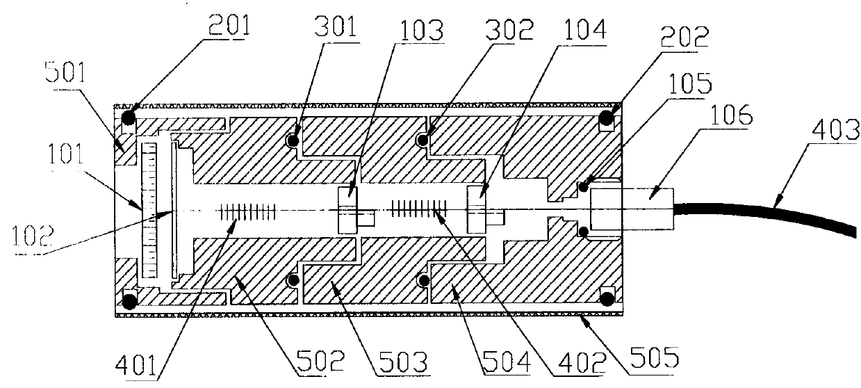
[0017] Such as figure 1 As shown, a fiber grating osmometer includes an outer cylinder 505, permeable stone bases 501 and end plugs 504 respectively arranged at both ends of the outer cylinder 505, and a temperature sensing device which is arranged in the outer cylinder 505 and is threadedly connected with the end plugs 504. The fiber grating cavity 503, the pressure-sensitive fiber grating cavity 502 set in the outer cylinder 505 and screwed to the permeable stone base 501; wherein, the permeable stone base 501 is hollow inside, and the permeable stone 101 is arranged inside, and the end plug 504 A through hole is provided, and an armored fixing structure 106 sc...


PUM


Abstract

The invention relates to a fiber grating osmometer comprising an outer cylinder, a porous stone base, an end plug, a temperature sensing grating chamber and a pressure sensing grating chamber. The porous stone base and the end plug are arranged at two ends of the outer cylinder, respectively. The temperature sensing grating chamber is arranged in the outer cylinder and connected with the end plug. The pressure sensing grating chamber is arranged in the outer cylinder and connected with the porous stone base. A porous stone is arranged in the hollow porous stone base. A through hole is formed in the end plug and internally provided with a sheath fixing structure used for fixing an optical fiber. The temperature sensing grating chamber and the pressure sensing grating chamber are arranged in the outer cylinder and connected with each other. Fiber gratings, arranged in the chambers, are sequentially fixed in the center of a pressure sensing membrane, a fixing structure, of the pressure sensing grating, and a fixing structure of the temperature sensing grating. One end of the pressure sensing grating chamber is provided with the pressure sensing membrane, and the other end of the pressure sensing grating chamber is provided with the fixing structure of the pressure sensing grating. The fixing structure of the temperature sensing grating is arranged at one end of the temperature sensing grating chamber. The fiber grating osmometer has the advantages of simple structure, manufacturing simplicity and high accuracy.

Description

Technical field: [0001] The invention belongs to the field of optical fiber sensing and relates to an optical fiber grating piezometer. technical background [0002] Piezometers are mainly used for long-term measurement of liquid and pore water pressure in piezometers, boreholes, dams, pipelines and pressure vessels. However, the widely used pressure measuring instruments are mainly electronic sensors, and the electronic sensors have poor anti-electromagnetic interference ability. Explosion, causing an accident. [0003] Fiber Bragg grating sensors can completely avoid the above problems, so they are more and more widely used. Many domestic researchers have studied fiber grating piezometers, such as the dual-fiber reflective hydraulic piezometer designed by the Chinese patent [Patent No.: ZL 200820151228.0], which has high measurement accuracy, but the design principle and manufacturing process are very complicated, so it is difficult to Conducive to product promotion. ...

Claims


Application Information

Patent Timeline
Patent Type & Authority Applications(China)
IPC IPC(8): G01L11/02
Inventor 陈庆根王云鹏
Owner 杭州珏光物联网科技有限公司
Learn More