A rolling stone impact field simulation test device

A simulation test and on-site technology, which is applied in the field of rolling stone impact field simulation test devices, can solve the problems of the influence of the size of the impact force of the rolling stone, the inability to accurately test the impact force of the rolling stone, and the unclear distribution position of the force sensor, etc., and achieve the effect of high test accuracy

Active Publication Date: 2017-06-30
裴向军 +1
View PDF6 Cites 0 Cited by
  • Summary
  • Abstract
  • Description
  • Claims
  • Application Information

AI Technical Summary

Problems solved by technology

In the rolling stone impact test device disclosed in this patent document, the specific distribution position of the force sensors is not clear, and the specific distribution of the force sensors will affect the test accuracy. The rolling stone touches the center and surroundings of the upper baffle, and the measured rolling stone impact force is different. As a result, the theoretical data measured by the entire test device is inaccurate. In addition, the impact velocity of the rolling stone is difficult to simulate, which will also have an impact on the impact force of the rolling stone obtained from the test. As a result, the entire test device cannot accurately measure the impact force of the rolling stone and cannot be used for on-site construction. Engineering provides accurate theoretical reference

Method used


Image

  • A rolling stone impact field simulation test device
  • A rolling stone impact field simulation test device
  • A rolling stone impact field simulation test device

Examples


Embodiment 1

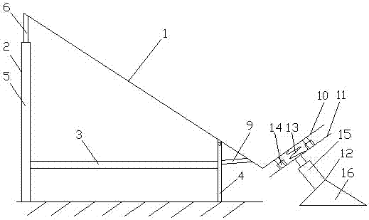
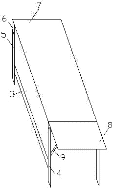
[0051] A rolling stone impact field simulation test device, including blocking parts, also includes a track part in contact with the blocking part, the track part is composed of a track 1 and a bracket, and the bracket is composed of a rear stand 2, a connecting rod 3 and a front stand 4. One end of the connecting rod 3 is connected to the rear stand 2, and the other end is connected to the front stand 4. The rear stand 2 is composed of a telescopic column 5 and a telescopic rod 6 slidingly connected in the telescopic column 5. The track 1 is composed of a rear sliding surface 7 and a front sliding surface 8, the rear end of the rear sliding surface 7 is fixedly connected with the telescopic rod 6, the front end is hinged with the front stand 4, and the rear end of the front sliding surface 8 is connected with the front stand 4. Hinged, the front end is connected with the middle part of the front stand 4 through the shrinkage part 9; the blocking part is composed of an upper ba...

Embodiment 2

[0054] A rolling stone impact field simulation test device, including blocking parts, also includes a track part in contact with the blocking part, the track part is composed of a track 1 and a bracket, and the bracket is composed of a rear stand 2, a connecting rod 3 and a front stand 4. One end of the connecting rod 3 is connected to the rear stand 2, and the other end is connected to the front stand 4. The rear stand 2 is composed of a telescopic column 5 and a telescopic rod 6 slidingly connected in the telescopic column 5. The track 1 is composed of a rear sliding surface 7 and a front sliding surface 8, the rear end of the rear sliding surface 7 is fixedly connected with the telescopic rod 6, the front end is hinged with the front stand 4, and the rear end of the front sliding surface 8 is connected with the front stand 4. Hinged, the front end is connected with the middle part of the front stand 4 through the shrinkage part 9; the blocking part is composed of an upper ba...

Embodiment 3

[0060] A rolling stone impact field simulation test device, including blocking parts, also includes a track part in contact with the blocking part, the track part is composed of a track 1 and a bracket, and the bracket is composed of a rear stand 2, a connecting rod 3 and a front stand 4. One end of the connecting rod 3 is connected to the rear stand 2, and the other end is connected to the front stand 4. The rear stand 2 is composed of a telescopic column 5 and a telescopic rod 6 slidingly connected in the telescopic column 5. The track 1 is composed of a rear sliding surface 7 and a front sliding surface 8, the rear end of the rear sliding surface 7 is fixedly connected with the telescopic rod 6, the front end is hinged with the front stand 4, and the rear end of the front sliding surface 8 is connected with the front stand 4. Hinged, the front end is connected with the middle part of the front stand 4 through the shrinkage part 9; the blocking part is composed of an upper ba...


PUM


Abstract

The invention discloses a rolling stone impacting scene simulation test device. A rail component is composed of a rail and a bracket. The bracket is composed of a rear support, a connecting rod and a front support. One end of the connecting rod is connected with the rear support, and the other end of the connecting rod is connected with the front support. The rear support is composed of a telescopic column and a telescopic rod. The rail is composed of a rear sliding face and a front sliding face, the rear end of the rear sliding face is connected with the telescopic rod, and the front end of the rear sliding face is hinged with the front frame. The rear end of the front sliding face is hinged with the front frame, and the front end of the front sliding face is connected with the middle of the front support through a shrinking part. A stopping member comprises an upper retainer and a lower retainer which are connected through a compressing spring. A plurality of pressure sensors are arranged in a clearance which is formed between the upper retainer and the lower retainer. Area of the pressure sensors accounts for 1 / 4-3 / 4 of that of the upper retainer. A base bracket is composed of a telescopic part and a support. The one end of the telescopic part is rotationally connected with the lower retainer, and the other end of the telescopic part is fixedly connected with the support. By the use of the rolling stone impacting scene simulation test device, the falling impact of the rolling stones is simulated in a multi-angle manner, and an accurate theoretical reference is provided for rolling stone protection engineering.

Description

technical field [0001] The invention relates to the technical field of prevention and control of geological disasters, in particular to an on-site simulation test device for the impact of rolling stones. Background technique [0002] In geological disasters, landslides, collapses, and debris flows will cause serious damage to public roadbeds, and the measures often taken for engineering slope protection are slope protection and support structure protection. Slope protection includes plastering such as mortar or composite soil, shotcrete, shotcrete, mortar-built rubble wall, anchor-spray slope protection, anchor-spray net slope protection, etc. Such measures are mainly used to protect the weathering and spalling of rocks on the slope surface of excavation, chipping, and a small amount of falling rocks and blocks. The slope to be protected should have sufficient stability, and the unstable slope should be supported first and then protected. There are many types of protection...

Claims


Application Information

Patent Timeline
Patent Type & Authority Patents(China)
IPC IPC(8): G01M7/08
Inventor 裴向军袁进科
Owner 裴向军
Why Eureka
Try Eureka