A Distributed Multi-Sensor Multi-Target Passive Localization Method Based on Projection Strategy

A multi-sensor, passive positioning technology used in positioning, instruments, radio wave measurement systems, etc.

Active Publication Date: 2017-02-15
LESHAN NORMAL UNIV
View PDF5 Cites 0 Cited by
  • Summary
  • Abstract
  • Description
  • Claims
  • Application Information

AI Technical Summary

Problems solved by technology

The passive positioning method of the present invention solves the measurement data association problem faced in distributed multi-sensor multi-target passive positioning, and has the advantages of strong real-time performance and high positioning accuracy

Method used


Image

  • A Distributed Multi-Sensor Multi-Target Passive Localization Method Based on Projection Strategy
  • A Distributed Multi-Sensor Multi-Target Passive Localization Method Based on Projection Strategy
  • A Distributed Multi-Sensor Multi-Target Passive Localization Method Based on Projection Strategy

Examples


Embodiment 1

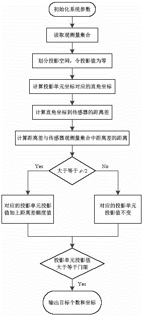
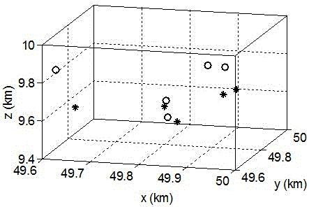
[0052] As a preferred embodiment of the present invention, this embodiment mainly adopts the method of simulation experiment for verification, and all steps and conclusions are verified on MATLABR2012a. Concrete embodiment steps are as follows:

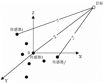
[0053] A. Preparing the sensors: dispersed within a specific detection area sensors, the number of sensors satisfies ;

[0054] B. Set the coordinate system: set a Cartesian rectangular coordinate system, the origin of the coordinate system is located at the first sensor, and the sensor is at The position coordinates of the Cartesian rectangular coordinate system are , ,in, ; Sensors 2, 3, and 4 are located at km, km and At km, sensors 5~11 are randomly scattered in the triangular area determined by sensors 2, 3 and 4; the detection area of ​​the sensors is [XX,YY,ZZ]=[50,50,10]km;

[0055] C. Obtain data: take the first sensor as the main station, other sensors as auxiliary stations, and slave sensors , Rea...

Embodiment 2

[0071] As a preferred embodiment of the present invention, this embodiment mainly adopts the method of simulation experiment for verification, and all steps and conclusions are verified on MATLABR2012a. Concrete embodiment steps are as follows:

[0072] A. Preparing the sensors: dispersed within a specific detection area sensors, the number of sensors satisfies ;

[0073] B. Set the coordinate system: set a Cartesian rectangular coordinate system, the origin of the coordinate system is located at the first sensor, and the sensor is at The position coordinates of the Cartesian rectangular coordinate system are , ,in, ; Sensors 2, 3, and 4 are located at km, km and At km, sensors 5~21 are randomly scattered in the triangular area determined by sensors 2, 3 and 4; the detection area of ​​the sensors is [XX,YY,ZZ]=[50,50,10]km;

[0074] C. Obtain data: take the first sensor as the main station, other sensors as auxiliary stations, and slave sensors , Rea...

Embodiment 3

[0090] As a preferred embodiment of the present invention, this embodiment mainly adopts the method of simulation experiment for verification, and all steps and conclusions are verified on MATLABR2012a. Concrete embodiment steps are as follows:

[0091] A. Preparing the sensors: dispersed within a specific detection area sensors, the number of sensors satisfies ;

[0092] B. Set the coordinate system: set a Cartesian rectangular coordinate system, the origin of the coordinate system is located at the first sensor, and the sensor is at The position coordinates of the Cartesian rectangular coordinate system are , ,in, ; Sensors 2, 3, and 4 are located at km, km and At km, sensors 5~31 are randomly scattered in the triangular area determined by sensors 2, 3 and 4; the detection area of ​​the sensors is [XX,YY,ZZ]=[50,50,10]km;

[0093] C. Obtain data: take the first sensor as the main station, other sensors as auxiliary stations, and slave sensors , Rea...


PUM


Abstract

The invention discloses a projection strategy based distributed multi-sensor multi-target passive locating method, and relates to the technical field of passive location. The projection strategy based distributed multi-sensor multi-target passive locating method comprises the steps of projecting observed values obtained by sensors to a projection space through a range difference equation, and accumulating amplitude values of target echoes obtained by different sensors in the projection space. The existence of the targets and the positions of the targets are judged through adopting threshold detection for the accumulated values in the projection space, so that detection and location for multiple targets are realized. The projection strategy based distributed multi-sensor multi-target passive locating method solves the difficulty of measuring data association, and is low in calculation complexity and strong in real-time performance.

Description

technical field [0001] The invention belongs to the technical field of passive positioning, and more specifically relates to a distributed multi-sensor multi-target passive positioning method based on a projection strategy. Background technique [0002] Distributed multi-sensor passive positioning uses multiple sensors to receive signals reflected from targets for positioning. Since the sensor itself does not radiate electromagnetic waves, it has the advantages of good concealment, anti-electromagnetic interference, electromagnetic stealth, and strong low-altitude detection capabilities, and has broad application prospects in military reconnaissance, surveillance, and other fields. [0003] The existing distributed passive positioning methods mainly include: direction finding cross positioning method, time difference of arrival positioning method, Doppler frequency difference positioning method and so on. [0004] The time difference of arrival positioning method has strong...

Claims


Application Information

Patent Timeline
Patent Type & Authority Patents(China)
IPC IPC(8): G01S5/00
CPCG01S5/00
Inventor 樊玲周昌海
Owner LESHAN NORMAL UNIV
Why Eureka
Try Eureka