
Gap design method used for automobile covering part die

A technology for automotive panels and design methods, applied in the direction of calculation, 3D modeling, special data processing applications, etc., can solve problems such as unexplained, unexplained how to design the surface, etc., to achieve convenient and flexible use, ensure continuity and quality , the effect of simple operation

Active Publication Date: 2014-12-10
山东山大华天软件有限公司
View PDF6 Cites 11 Cited by
  • Summary
  • Abstract
  • Description
  • Claims
  • Application Information

AI Technical Summary

Problems solved by technology

[0006] The patent application number 201310334085.2 "A Convex Forming Method for Drawing Dies of Automobile Panels" provides a forming method. Although the method calculates the boundary line of the convex-concave feature surface and divides the convex-concave features, it maintains the The convex feature surface remains unchanged, but it does not explain how to design the surface of the hollowed out part; in addition, it does not explain how to transition between the hollowed out part surface and the unchanged convex feature surface, and how to calculate the transition surface; finally, This method only belongs to the open-cut treatment of a single concave feature, and it is difficult to solve the complex situation in the research and matching. For example, the edge of the die needs to be opened due to the deformation of the die. , to increase the fillet processing for the convex fillet that only plays the role of supporting material, to reduce the fillet treatment for the concave fillet, and to open the space for the easy-to-interference surface

Method used


Image

  • Gap design method used for automobile covering part die
  • Gap design method used for automobile covering part die
  • Gap design method used for automobile covering part die

Examples


Embodiment 1

[0068] (1) Read the parametric three-dimensional surface model of the automobile panel into the computer, analyze the file format, and obtain the surface primitives, topological structure and parameter information of the surface model;

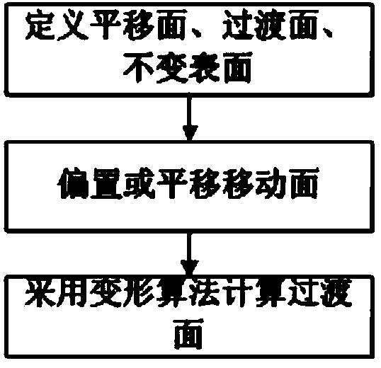
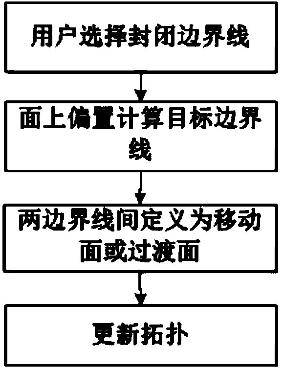
[0069] (2) The implementation steps of the die edge opening processing are: the user selects the intersection line between the product surface and the non-product surface through the interactive operation in the graphics area, that is, several edge lines on the outer periphery of the product, and connects end to end to form a closed and continuous outer peripheral edge line ; Then, set the following parameters: the adjustment amount is the offset or translation distance of the moving surface when the air is open, the open direction is the direction of the translation offset of the moving surface, and the area value is the length value used for the surface offset to form the transition surface , the color and layer of the surface after blanking,...


PUM


Abstract

The invention discloses a gap design method used for an automobile covering part die. The method comprises the following steps: inputting a covering part parameterized three-dimensional curved surface module, reading parameter patch primitives as well as a topological structure and characteristic parameters thereof which are comprised by the three-dimensional curved surface module; according to the requirements for designing a female die or a male die, hollowing out the female die edge, convex hulls and easily-interfered molded surface in the obtained three-dimensional curved surface module; strongly pressing blank holder management surfaces and pressing material core areas of the male die or the female die; performing enlargement treatment on convex fillets having the material supporting function in a pressing material surface covering area, performing reduction treatment on concave fillets, and recreating a new fillet surface; outputting the three-dimensional curved surface module subjected to gap design according to the input document structure of the three-dimensional curved surface. The method has the characteristics that the operation is simple, the algorithm is simple and convenient, the deformation quality and efficiency are high, and the requirements for the adjustment of various gaps of die design can be well met.

Description

technical field [0001] The invention relates to a clearance design method for an automobile panel mold. Background technique [0002] The design and manufacturing process of stamping dies for automotive panels mainly includes: obtaining the original surface model of the panel, modifying or adjusting the surface shape according to the stamping process, then compiling the NC machining program of the mold surface, using CNC machine tools to process the mold surface, and finally the fitter in the physical Root cleaning, research and matching, and debugging are carried out on the mold. [0003] At present, large and medium-sized mold companies generally spend a long time in the final research, assembly and debugging, and the labor intensity of workers is high, time-consuming, laborious, and production efficiency is low. The tasks of root cleaning and research and matching are too large. The reason why the adjustment of the 3D mold surface is not in place is that the current maj...

Claims


Application Information

Patent Timeline
Patent Type & Authority Applications(China)
IPC IPC(8): G06F17/50G06T17/00
Inventor 梅敬成张道忠苏新新赵晓峰魏威狄林林王会林陈荣昌
Owner 山东山大华天软件有限公司
Learn More