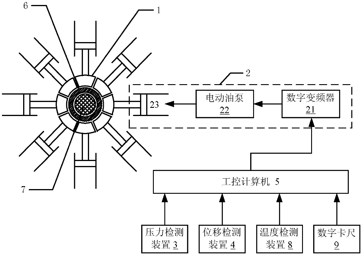
Pressure joint system

A compression molding and pressure technology, which is applied in the field of high-voltage insulator installation, can solve the problems of many influencing factors, low crimping efficiency, and difficulty in applying optimal pressure.

Active Publication Date: 2014-12-10
BEIJING RAILWAY INST OF MECHANICAL & ELECTRICAL ENG
View PDF4 Cites 4 Cited by
  • Summary
  • Abstract
  • Description
  • Claims
  • Application Information

AI Technical Summary

Problems solved by technology

Due to many influencing factors, it is difficult to apply optimal p

Method used


Image

  • Pressure joint system

Examples


Embodiment Construction

[0028] The present invention is described below based on examples, but the present invention is not limited to these examples. In the following detailed description of the invention, some specific details are set forth in detail. The present invention can be fully understood by those skilled in the art without the description of these detailed parts. In order not to obscure the essence of the present invention, well-known methods, procedures, procedures, components and circuits have not been described in detail.

[0029] Additionally, those of ordinary skill in the art will appreciate that the drawings provided herein are for illustrative purposes and are not necessarily drawn to scale.

[0030] Unless the context clearly requires, throughout the specification and claims, "comprises", "comprises" and similar words should be interpreted in an inclusive sense rather than an exclusive or exhaustive meaning; that is, "including but not limited to" meaning.

[0031] In the descr...


PUM


Abstract

The invention discloses a pressure joint system used for pressure joint of insulator core rods and hardware fittings. The pressure joint system comprises a plurality of pressing dies, a pressing die driving device, a displacement detection device and an industrial personal computer. The plurality of pressing dies are arranged around a center of a circle and used for radially moving to extrude the hardware fittings; the pressing die driving device is used for driving the pressing dies to move radially; the pressure detection device is connected with the pressing die driving device and used for detecting pressure applied by the pressing dies; the displacement detection device is used for detecting radial displacement of the pressing dies; the industrial personal computer is respectively connected with the pressing die driving device, the pressure detection device and the displacement detection device and used for controlling the pressing die driving device according to the pressing die radial displacement acquired by the displacement detection device to extrude the hardware fittings by a preset displacement step by step until the pressure detection device detects that pressure stress applied by the pressing dies reaches a preset threshold. The pressure joint system has the advantages that the fact that pressure for pressure joint meets mounting requirements can be guaranteed, and pressure joint efficiency is improved.

Description

technical field [0001] The invention relates to a high-voltage insulator installation technology, in particular to a crimping system for crimping insulator core rods and fittings. Background technique [0002] The post insulator for the roof of the electrified railway plays the role of supporting the pantograph and high-voltage switch and insulating it from the grounded car body. Its nominal working voltage is 25kV. This kind of insulator needs to have high mechanical strength and super long creepage distance. At present, the composite insulation structure of glass fiber resin core rod and silicone rubber jacket is generally used. [0003] Both ends of the mandrel need to be fitted with hardware so that the insulator can be fastened to the roof, pantograph and high voltage switch. At present, the methods of installing fittings include bonding, wedging, threading, crimping, etc., and the crimping method is more commonly used. [0004] When crimping, insert the mandrel into ...

Claims


Application Information

Patent Timeline
IPC IPC(8): H01B19/00
Inventor 黎莎王乐仁
Owner BEIJING RAILWAY INST OF MECHANICAL & ELECTRICAL ENG
Why Eureka
Try Eureka