Electromagnetic relay

An electromagnetic relay and magnetic circuit technology, applied in the direction of electromagnetic relays, electromagnetic relay details, relays, etc., can solve the problems of troublesome installation of the push block, failure to restore the initial state, damage and scrapping of the moving reed, etc.

Inactive Publication Date: 2014-12-10
浙江凡华电子股份有限公司
View PDF8 Cites 1 Cited by
  • Summary
  • Abstract
  • Description
  • Claims
  • Application Information

AI Technical Summary

Problems solved by technology

There are two deficiencies in the actual application of this electromagnetic relay: 1. When installing the push block, one end of the push block needs to be connected to the magnetic circuit part, and then the moving reed is moved away from the push block, and then Insert the positioning rod into the round hole of the moving reed, and finally put the push block on the upper end of the outer wall of the cavity, so the installation of the push block is not only troublesome, but also if the assembler moves the force of the move reed during the installation of the push block If it is used too much, it may cause excessive deformation of the moving reed and cannot return to the original state, resulting in damage to the moving reed; During the long-term working process, the moving reed will gradually heat up under the action of current and arc, so that the rebound force of the moving reed will become smaller and smaller. When the rebound force of the moving reed decreases to a certain extent, There may be a contact connection between the moving reed and the normally open static reed, so that the moving reed cannot be reset, and eventually the electromagnetic relay cannot work normally

Method used


Image

  • Electromagnetic relay
  • Electromagnetic relay
  • Electromagnetic relay

Examples


Embodiment Construction

[0015] The electromagnetic relay of the present invention will be further described in detail below in conjunction with the accompanying drawings and specific embodiments.

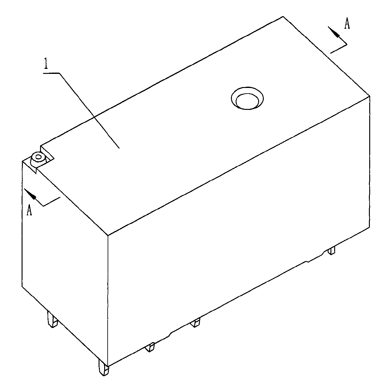
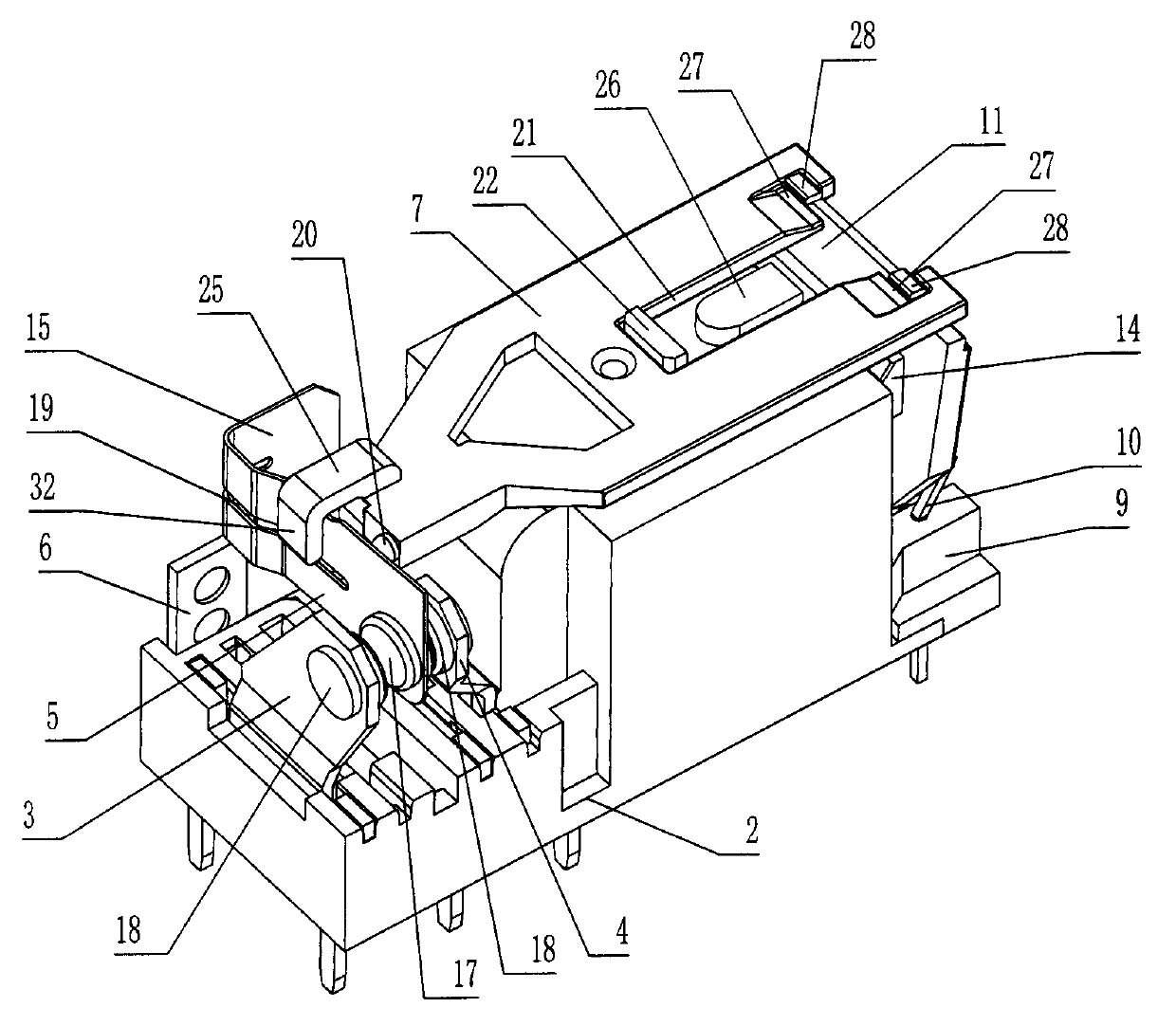
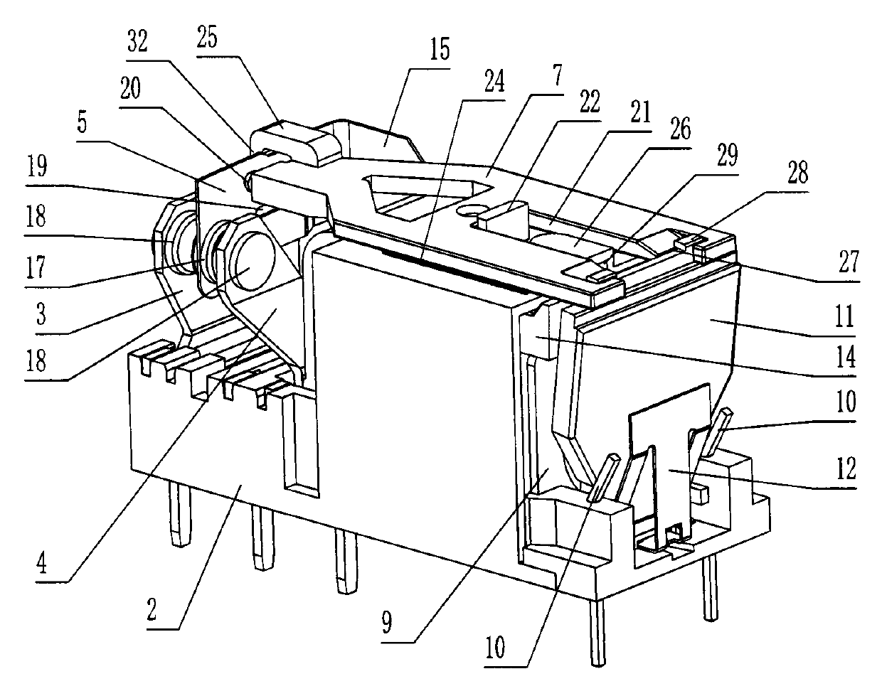
[0016] Such as Figure 1 to Figure 7 As shown, in this specific embodiment, the electromagnetic relay of the present invention includes a housing 1, a base 2, a push block 7, a contact part and a magnetic circuit part, and the contact part includes a normally open static reed 3 and a normally closed static reed 4 , moving reed 5 and welding piece 6, the magnetic circuit part includes coil 8, coil frame 9, coil lead-out rod 10, armature 11, pressure reed 12 and yoke 14 connected with iron core 13, normally open static reed 3, The normally closed static reed 4 and the welding piece 6 are installed on the left part of the base 2, the movable reed 5 is located between the normally open static reed 3 and the normally closed static reed 4, and the movable reed 5 is provided with a movable contact 17 , the norma...


PUM


Abstract

The invention discloses an electromagnetic relay comprising a housing, a base, a push block, a contact portion and a magnetic circuit portion. The base is provided with a cavity. The contact portion comprises a moving spring. The push block is arranged over the outer wall of the cavity. The middle of the push block is provided with a limiting slot. A limiter block capable of sliding side to side in the limiting slot is arranged at the upper end of the outer wall of the cavity. Limiter strips in a pair are arranged at the top of an inner cavity of the housing. The limiter strips are arranged over the push block in front and rear of the limiting slot respectively. Slide strips in a pair are arranged at the lower end of the push block. The slide strips press to the upper end of the outer wall of the cavity in front and rear of the limiting slot respectively. A pull rod is arranged at the left end of the push block. The left end of the pull rod is provided with a hook; the hook crosses the moving spring through the pull rod and is arranged on the left side of the moving spring. The electromagnetic relay has the advantages that the push block is convenient to mount, the moving spring is effectively avoided being damaged and scrapped during mounting of the push block, and the electromagnetic relay can assist in resetting the moving spring.

Description

technical field [0001] The invention relates to an electronic control device, in particular to an electromagnetic relay. Background technique [0002] Electromagnetic relays can control high-voltage and high-current circuits with low voltage and low current, and can also realize remote control and production automation, playing an increasingly important role in modern life. At present, on the website of the State Intellectual Property Office of China, a utility model patent with the authorized announcement number "CN 2383205Y" discloses a "low height and small high-power electromagnetic relay", which includes a housing, a base, a push block, a contact part and For the magnetic circuit part, there is a cavity on the base, the magnetic circuit part is installed on one side of the base and contained by the cavity, the contact part is installed on the other side of the base, the contact part includes a moving reed, and the push block is sleeved on the outer wall of the cavity A...

Claims


Application Information

Patent Timeline
Patent Type & Authority Applications(China)
IPC IPC(8): H01H50/18
Inventor 王照杉
Owner 浙江凡华电子股份有限公司
Why Eureka
Try Eureka