Quantum key distribution (QKD) system synchronization method and device

A quantum key distribution and synchronization device technology, applied to key distribution, can solve the problem that QKD links cannot run at the same time, and achieve the effects of easy identification of link quality, low device cost, and convenient mass production

Active Publication Date: 2014-12-10
QUANTUMCTEK
View PDF10 Cites 18 Cited by
  • Summary
  • Abstract
  • Description
  • Claims
  • Application Information

AI Technical Summary

Problems solved by technology

[0019] The present invention provides a synchronization method and device for a quantum key distribution system, which is used to solve the synchronization light reflection caused by the same wavelength of synchronization light between Alice of QKD device_L and Alice of QKD device_R in a duplex QKD system Will cause the problem that two QKD links cannot run at the same time

Method used


Image

  • Quantum key distribution (QKD) system synchronization method and device
  • Quantum key distribution (QKD) system synchronization method and device
  • Quantum key distribution (QKD) system synchronization method and device

Examples


Embodiment 1

[0066] Embodiment one (using synchronous optical lasers of two different wavelengths)

[0067] Option1 (the wavelength of the synchronization light sent by Alice is determined by the control module):

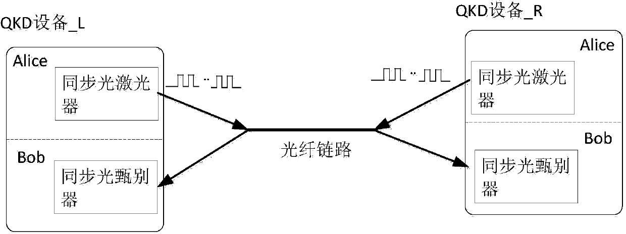
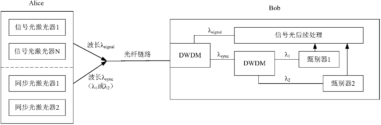
[0068] Such as Figure 6 As shown, Alice in QKD device_L and QKD device_R are equipped with two synchronous optical lasers—synchronous optical laser 1 and synchronous optical laser 2, wherein synchronous optical laser 1 fixedly transmits synchronous optical sync1 with a wavelength of λ 1 , the synchronous optical laser 2 fixedly transmits the synchronous optical sync2 with a wavelength of λ 2 , and λ 1 ≠λ 2 . Both QKD equipment_L and QKD equipment_R’s Bob are equipped with two-stage optical filter devices. The first-stage optical filter device can separate signal light and synchronous light, and the second-stage optical filter device can separate two channels of synchronous light with different wavelengths. light, such as image 3 shown. The second-stage optical filter ...

Embodiment 2

[0078] Embodiment two (using a synchronous optical laser with variable wavelength)

[0079] Option1 (the wavelength of the synchronization light sent by Alice is determined by the control module):

[0080] Such as Figure 7 As shown, Alice in QKD device_L and QKD device_R both use a wavelength-tunable synchronous optical laser, and the wavelength-tunable synchronous optical laser can send synchronous optical sync1 with a wavelength of λ 1 , can also send synchronous light sync2, the wavelength is λ 2 , and λ 1 ≠λ 2 , the wavelength of which transmits synchronous light is scheduled by the control module. Both QKD equipment_L and QKD equipment_R’s Bob are equipped with two-stage optical filter devices. The first-stage optical filter device can separate signal light and synchronous light, and the second-stage optical filter device can separate synchronous light of different wavelengths. Such as image 3 shown. Send the separated two channels of synchronous light into the c...

Embodiment 3

[0088] Embodiment 3 (a synchronous optical laser with a different wavelength is used at both ends of the system respectively)

[0089] Such as Figure 8 As shown, QKD equipment_L and QKD equipment_R respectively use a synchronous optical laser with different wavelengths, and synchronous optical laser 1 fixedly transmits a wavelength of λ 1 The synchronous optical sync1, the synchronous optical laser 2 fixedly sends a wavelength of λ 2 The synchronization light sync2, and λ 1 ≠λ 2 . The Bob of QKD equipment_L and QKD equipment_R both use a first-stage optical filter device to separate signal light and synchronous light. The separated synchronous light is sent to the discriminator, and the discriminator 1 fixedly discriminates the central wavelength as λ 1 The synchronous light sync1, the discriminator 2 fixedly discriminates the central wavelength as λ 2 The synchronization light sync2.

[0090] The specific implementation is as follows: on the link between Alice in QKD ...


PUM


Abstract

The invention provides a quantum key distribution (QKD) system synchronization method. A quantum key distribution system is a duplex QKD system, Alices of QKD units at two ends of the duplex QKD system are capable of transmitting two kinds of synchronous light different in wave length, and the transmitted synchronous light is transmitted in the same optical fiber link, so that when two QKD links are operated on the optical fiber link, the wave length of the synchronous light on the two links is different, Bobs of the QKD units at two ends adopt a light filter to separate the synchronous light, and corresponding discriminators are adopted to have the synchronous light discriminated. The invention further provides a synchronization device of the quantum key distribution system. The quantum key distribution system synchronization method and device have the advantages that the synchronous light different in wavelength is adopted at two ends of the duplex QKD system respectively, so that the problem that the duplex QKD system cannot perform full-duplex operation due to reflection of the synchronous light is solved; the device is simple and convenient to operate and convenient for batch production.

Description

technical field [0001] The invention relates to the field of quantum secure communication, and in particular provides a synchronization method of a quantum key distribution system and a duplex QKD system based on the synchronization method. Background technique [0002] The fundamental difference between Quantum Key Distribution (QKD) and the classical key system is that it uses a single photon or entangled photon pair as the carrier of the key, and the basic principles of quantum mechanics guarantee that the process cannot be eavesdropped or Decipherability, thus providing a more secure key system. At present, the technology of using entangled photon pairs to realize quantum key distribution is not very mature, and there is still a considerable distance from practicality; while the technology of quantum key distribution based on single photon has been gradually matured. [0003] Quantum key distribution technology based on single photon usually has two encoding methods: po...

Claims


Application Information

Patent Timeline
Patent Type & Authority Applications(China)
IPC IPC(8): H04L9/08H04J14/02H04B10/25
CPCH04J14/0242H04L9/0852H04B10/2589
Inventor 唐世彪姚海涛贾云
Owner QUANTUMCTEK
Why Eureka
Try Eureka