A synchronization method and device for a quantum key distribution system
A quantum key distribution and synchronous optical technology, applied in key distribution, can solve the problem that QKD links cannot run at the same time, and achieve the effect of facilitating identification of link quality, facilitating mass production, and simple and convenient equipment operation
- Summary
- Abstract
- Description
- Claims
- Application Information
AI Technical Summary
Problems solved by technology
Method used
Image
Examples
Embodiment 1
[0066] Embodiment one (using synchronous optical lasers of two different wavelengths)
[0067] Option1 (the wavelength of the synchronization light sent by Alice is determined by the control module):
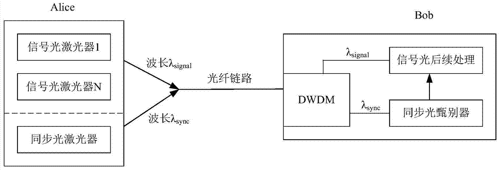
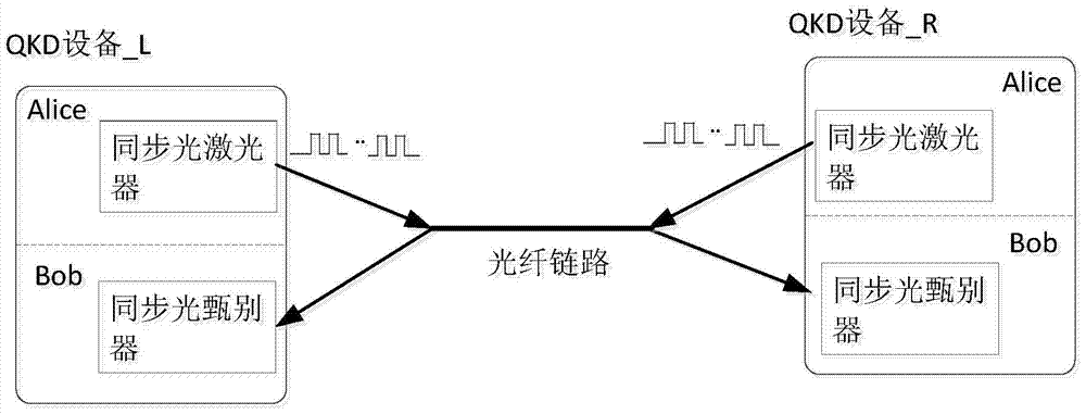
[0068] Such as Image 6 As shown, Alice in QKD device_L and QKD device_R are equipped with two synchronous optical lasers—synchronous optical laser 1 and synchronous optical laser 2, wherein synchronous optical laser 1 fixedly transmits synchronous optical sync1 with a wavelength of λ 1 , the synchronous optical laser 2 fixedly transmits the synchronous optical sync2 with a wavelength of λ 2 , and λ 1 ≠λ 2 . Both QKD equipment_L and QKD equipment_R’s Bob are equipped with two-stage optical filter devices. The first-stage optical filter device can separate signal light and synchronous light, and the second-stage optical filter device can separate two channels of synchronous light with different wavelengths. light, such as image 3 shown. The second-stage optical filter d...
Embodiment 2
[0078] Embodiment two (using a synchronous optical laser with variable wavelength)
[0079] Option1 (the wavelength of the synchronization light sent by Alice is determined by the control module):
[0080] Such as Figure 7 As shown, Alice in QKD device_L and QKD device_R both use a wavelength-tunable synchronous optical laser, and the wavelength-tunable synchronous optical laser can send synchronous optical sync1 with a wavelength of λ 1 , can also send synchronous light sync2, the wavelength is λ 2 , and λ 1 ≠λ 2 , the wavelength of which transmits synchronous light is scheduled by the control module. Both QKD equipment_L and QKD equipment_R’s Bob are equipped with two-stage optical filter devices. The first-stage optical filter device can separate signal light and synchronous light, and the second-stage optical filter device can separate synchronous light of different wavelengths. Such as image 3 shown. Send the separated two channels of synchronous light into the c...
Embodiment 3
[0088] Embodiment 3 (a synchronous optical laser with a different wavelength is used at both ends of the system respectively)
[0089] Such as Figure 8 As shown, QKD equipment_L and QKD equipment_R respectively use a synchronous optical laser with different wavelengths, and synchronous optical laser 1 fixedly transmits a wavelength of λ 1 The synchronous optical sync1, the synchronous optical laser 2 fixedly sends a wavelength of λ 2 The synchronization light sync2, and λ 1 ≠λ 2 . The Bob of QKD equipment_L and QKD equipment_R both use a first-stage optical filter device to separate signal light and synchronous light. The separated synchronous light is sent to the discriminator, and the discriminator 1 fixedly discriminates the central wavelength as λ 1 The synchronous light sync1, the discriminator 2 fixedly discriminates the central wavelength as λ 2 The synchronization light sync2.
[0090] The specific implementation is as follows: on the link between Alice in QKD ...
PUM
 Abstract
Description
Claims
Application Information
 - R&D
- Intellectual Property
- Life Sciences
- Materials
- Tech Scout
- Unparalleled Data Quality
- Higher Quality Content
- 60% Fewer Hallucinations
Browse by: Latest US Patents, China's latest patents, Technical Efficacy Thesaurus, Application Domain, Technology Topic, Popular Technical Reports.
© 2025 PatSnap. All rights reserved.Legal|Privacy policy|Modern Slavery Act Transparency Statement|Sitemap|About US| Contact US: help@patsnap.com


