

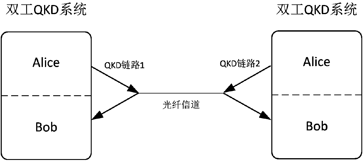
Quantum key distribution device used in duplex quantum key distribution system
A technology of quantum key distribution and key distribution system, which is applied to key distribution, can solve the problems of synchronous light reflection and increased system development cost, and achieve the effect of low development cost
- Summary
- Abstract
- Description
- Claims
- Application Information
AI Technical Summary
Problems solved by technology
Method used
Image

Examples
Embodiment 1
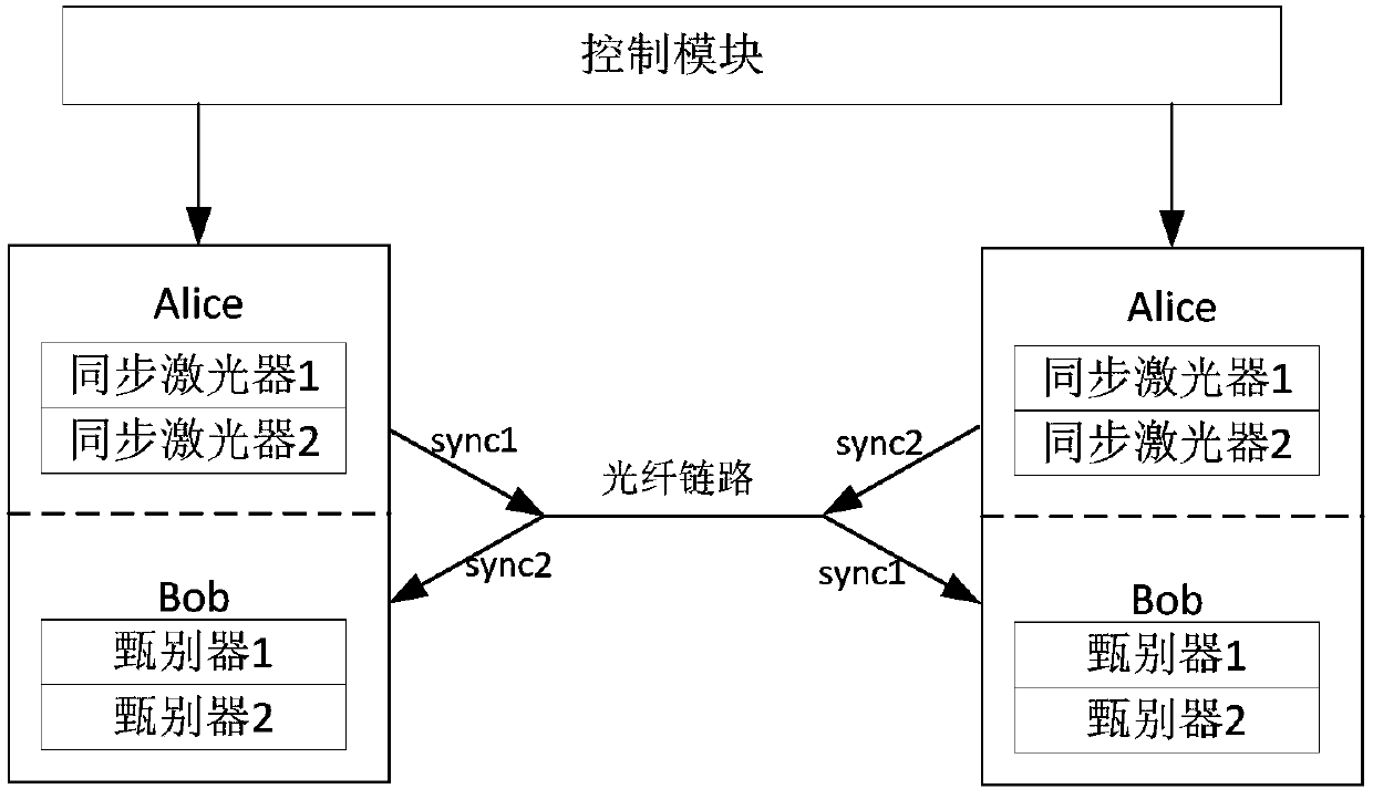
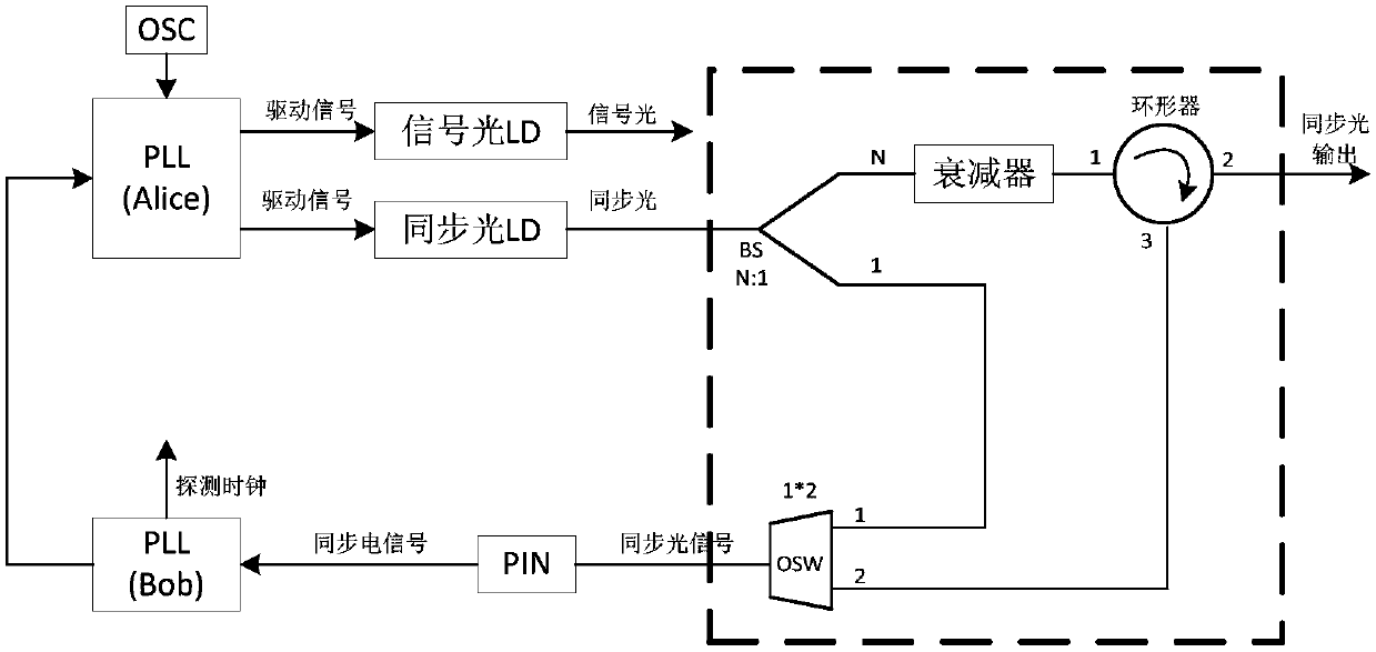
[0033] Such as image 3 As shown, in this embodiment, in the duplex QKD system, the two QKD devices paired have the same structure, and the synchronous light generating and receiving device of each QKD device includes a crystal oscillator (Oscillator, OSC), a sending end phase-locked loop (PhaseLocked Loop, PLL), synchronous optical laser (LD, Laser Diode), optical beam splitter BS (Beam Splitter), adjustable optical attenuator, circulator, optical switch OSW (Optical Switch), PIN tube, receiving end phase-locked loop .
[0034]The crystal oscillator is connected to the phase-locked loop at the sending end, the output end of the phase-locked loop at the sending end is connected to the synchronous optical laser, the output end of the synchronous optical laser is connected to the input end of the optical beam splitter, and the splitting ratio of the optical beam splitter is N:1 , the end of the optical beam splitter with a ratio of N is connected to the circulator port 1 throug...
Embodiment 2
[0050] In the duplex QKD system, the two devices that work in a pair adopt an unequal design scheme, that is, for the two QKD systems that work in a pair in the first embodiment, only the part that participates in the work is designed at each end, and no redundant part is designed. Duplex QKD system-L and duplex QKD system-R are respectively designed as follows:
[0051] Such as Figure 6 As shown, the synchronous optical generating device of one of the paired duplex QKD systems-L includes a crystal oscillator (Oscillator, OSC), a sending end phase-locked loop (Phase Locked Loop, PLL), a synchronous optical laser (LD, LaserDiode), an optical splitter Beamer BS (Beam Splitter), adjustable optical attenuator, circulator, optical switch OSW (OpticalSwitch), PIN tube, receiver phase-locked loop. The crystal oscillator is connected to the phase-locked loop at the sending end, and the output end of the phase-locked loop at the sending end is connected to a synchronous optical laser...
Embodiment 3
[0061] For ease of description, each QKD device that is paired with the same structure in Embodiment 1 is called "complete QKD device", and in Embodiment 2, only the part that participates in the work is designed, and each QKD device that does not design redundant parts is called As "the simplest QKD device", and the "simplest QKD device" that sends synchronous light is called "the simplest synchronous light sending QKD device", and the "simplest QKD device" that receives synchronous light is called "the simplest synchronous light receiving QKD device". device".
[0062] In the second embodiment, the paired two QKD devices all adopt the QKD device with simplified structure. In the actual application process, it is inevitable that one of the QKD devices fails. If there is no simplified QKD device with the same structure on site, it will affect the Use of a duplex QKD system.
[0063] In this embodiment, a complete QKD device and a minimal synchronous optical receiving QKD device...
PUM
 Abstract
Description
Claims
Application Information