Interlock detector with self-diagnosis function for an interlock circuit, and method for the self-diagnosis of the interlock detector

A technology of interlocking circuits and detectors, which is applied in the field of interlocking detectors, can solve problems such as voltage drop, and achieve the effect of saving cost and space

Active Publication Date: 2014-12-10
ROBERT BOSCH GMBH +1
View PDF6 Cites 8 Cited by
  • Summary
  • Abstract
  • Description
  • Claims
  • Application Information

AI Technical Summary

Problems solved by technology

Through the measuring resistor 4 of the interlock circuit 60, a voltage drop determined by the interlock signal 26 results

Method used


Image

  • Interlock detector with self-diagnosis function for an interlock circuit, and method for the self-diagnosis of the interlock detector
  • Interlock detector with self-diagnosis function for an interlock circuit, and method for the self-diagnosis of the interlock detector
  • Interlock detector with self-diagnosis function for an interlock circuit, and method for the self-diagnosis of the interlock detector

Examples


Embodiment Construction

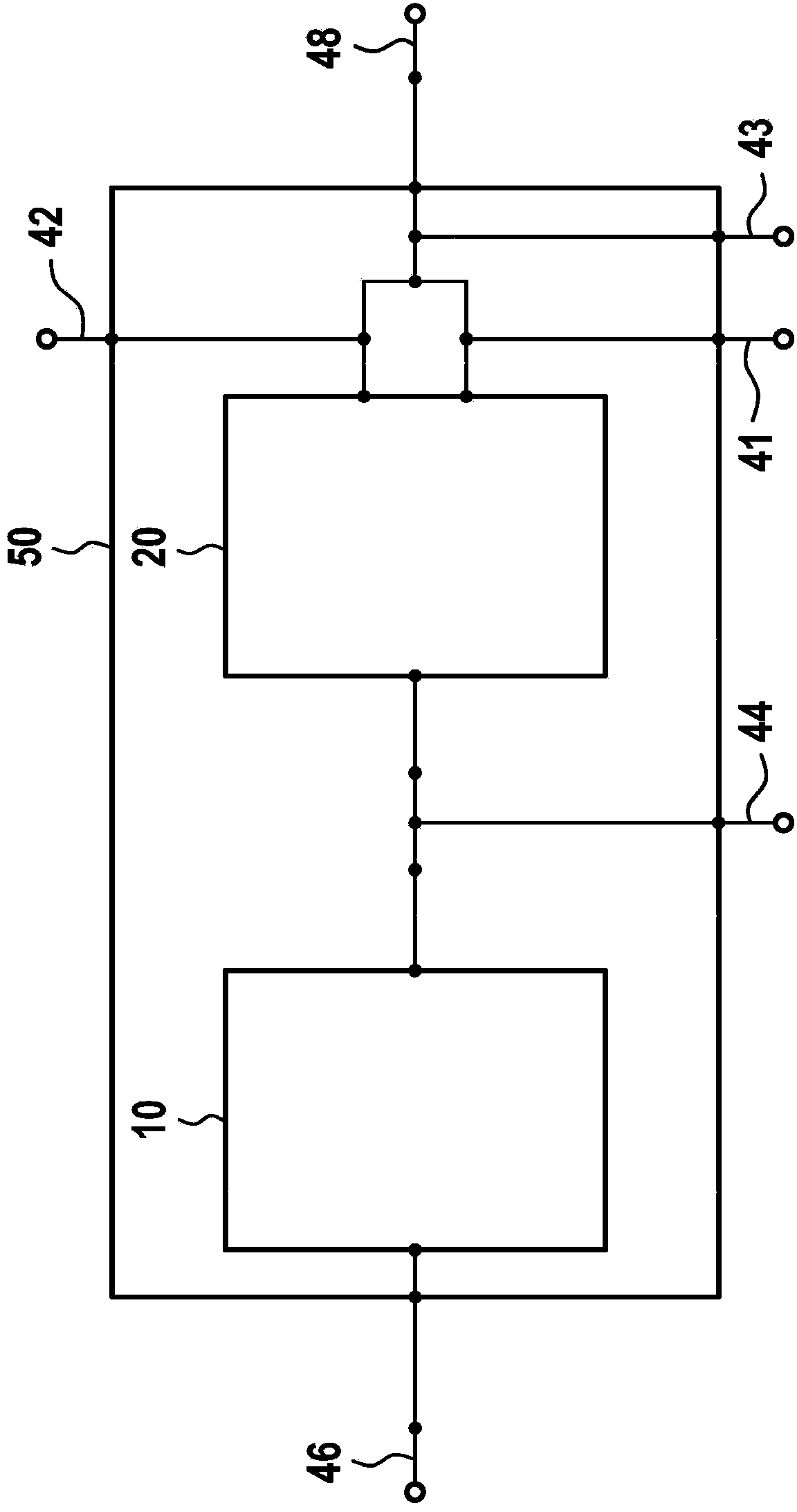
[0027] figure 2 A schematic diagram of an interlock detector 50 according to the invention is shown. The interlock detector 50 has a first input 48 via which the output signal of the interlock generator can be tapped and a first output 46 via which the output signal can be transmitted to a microprocessor. The first input 48 is connected to the first and second inputs of the differential amplifier 20 . The output of the differential amplifier 20 is connected to the input of the comparison circuit 10 . The output of comparison circuit 10 is connected to output 46 of interlock detector 50 . Furthermore, the illustrated interlock detector 50 according to the invention has four further second inputs 41 , 42 , 43 , 44 purely by way of example, via which a plurality of diagnostic signals can be fed into the circuit. The two second inputs 41 , 42 of interlock detector 50 are connected to one of the first or second inputs of a differential amplifier between input 48 of interlock de...


PUM


Abstract

The interlock detector (50) according to the invention comprises a first input (48), an output (46), a differential amplifier (20), the first and second input of which are connected to the first input (48) of the interlock detector (50), and a comparator circuit (10), the input of which is connected to the output of the differential amplifier (20) and the output of which is connected to the output (46) of the interlock detector (50). Furthermore, the interlock detector (50) comprises at least one second input (41, 42, 43, 44) to which a diagnosis signal is applied. The at least one second input (41, 42, 43, 44) is connected to the input of the comparator circuit (10), between the comparator circuit (10) and the differential amplifier (20), and / or to one of the first or second inputs of the differential amplifier (20), between the first input (48) of the interlock detector (50) and the differential amplifier (20). The invention further relates to a corresponding method and a corresponding interlock detector system.

Description

technical field [0001] The invention relates to an interlock detector for an interlock circuit implemented in a battery control device, which enables its own function check / diagnosis. Background technique [0002] According to document DE 10 2010 031 456 a method for shutting down an electrical network for safety reasons is known, in which an interlock circuit (also known as safety conductor loop, interlock or pilot line (Pilotlinie) or interlock circuit) is used. Lock or control wire (Pilotleitung)), when the safety of personnel is threatened by live parts, the electrical energy source belonging to the electrical network is shut off or disconnected from the electrical network by opening the interlock circuit. [0003] Interlock circuits, which are designed as signal loops, are therefore used in electrical networks, for example in vehicles with a rated voltage of more than 60 volts. The generation of a so-called interlock signal is generally carried out by a so-called int...

Claims


Application Information

Patent Timeline
Patent Type & Authority Applications(China)
IPC IPC(8): B60L3/00B60L3/04G05B23/02G01R31/00
CPCB60L3/0069B60L3/0046B60L3/12B60L3/04B60L58/10Y02T10/70G01R31/2827G01R31/2834G01R31/2884
Inventor T·舍德利希
Owner ROBERT BOSCH GMBH
Why Eureka
Try Eureka