Movable member control device and imaging device equipped with same

A technology of control devices and moving parts, which is applied in the directions of printing and printing devices, projection devices, components of TV systems, etc., can solve the problems of difficult voice coil motors, inability to miniaturize, and loss of freedom.

Active Publication Date: 2014-12-10
奥之心数字科技株式会社
View PDF9 Cites 0 Cited by
  • Summary
  • Abstract
  • Description
  • Claims
  • Application Information

AI Technical Summary

Problems solved by technology

[0003] However, in order to apply force to the position of the center of gravity of the movable part, a voice coil motor must be arranged, so the degree of freedom of arrangement is lost, and it cann

Method used


Image

  • Movable member control device and imaging device equipped with same
  • Movable member control device and imaging device equipped with same
  • Movable member control device and imaging device equipped with same

Examples


Example Embodiment

[0057] Next, an embodiment of the present invention will be described.

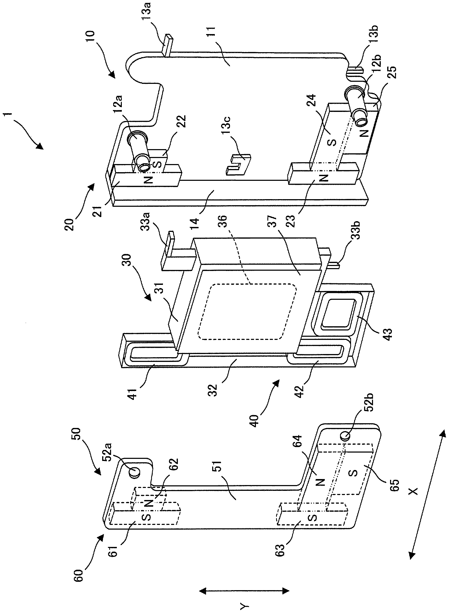
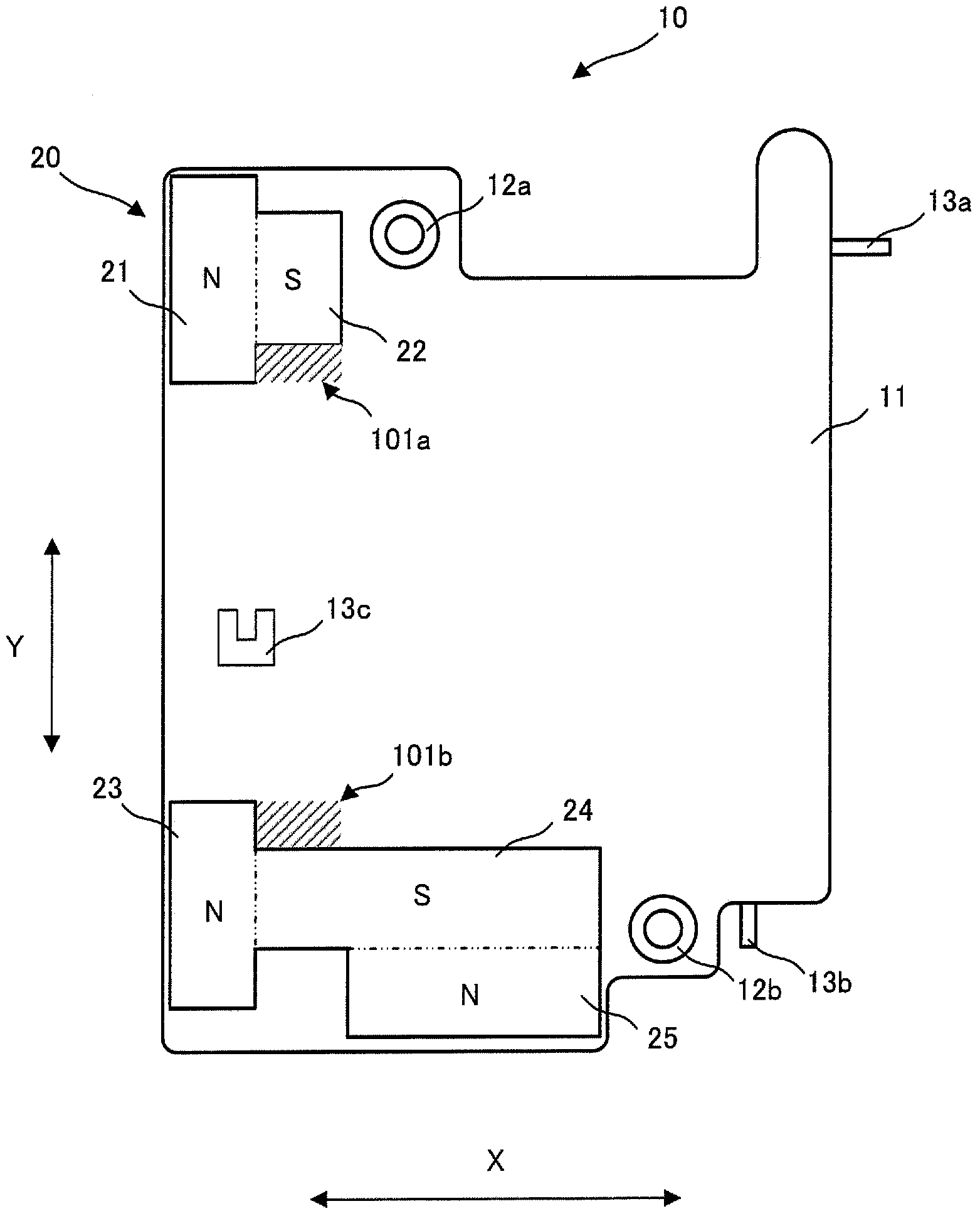
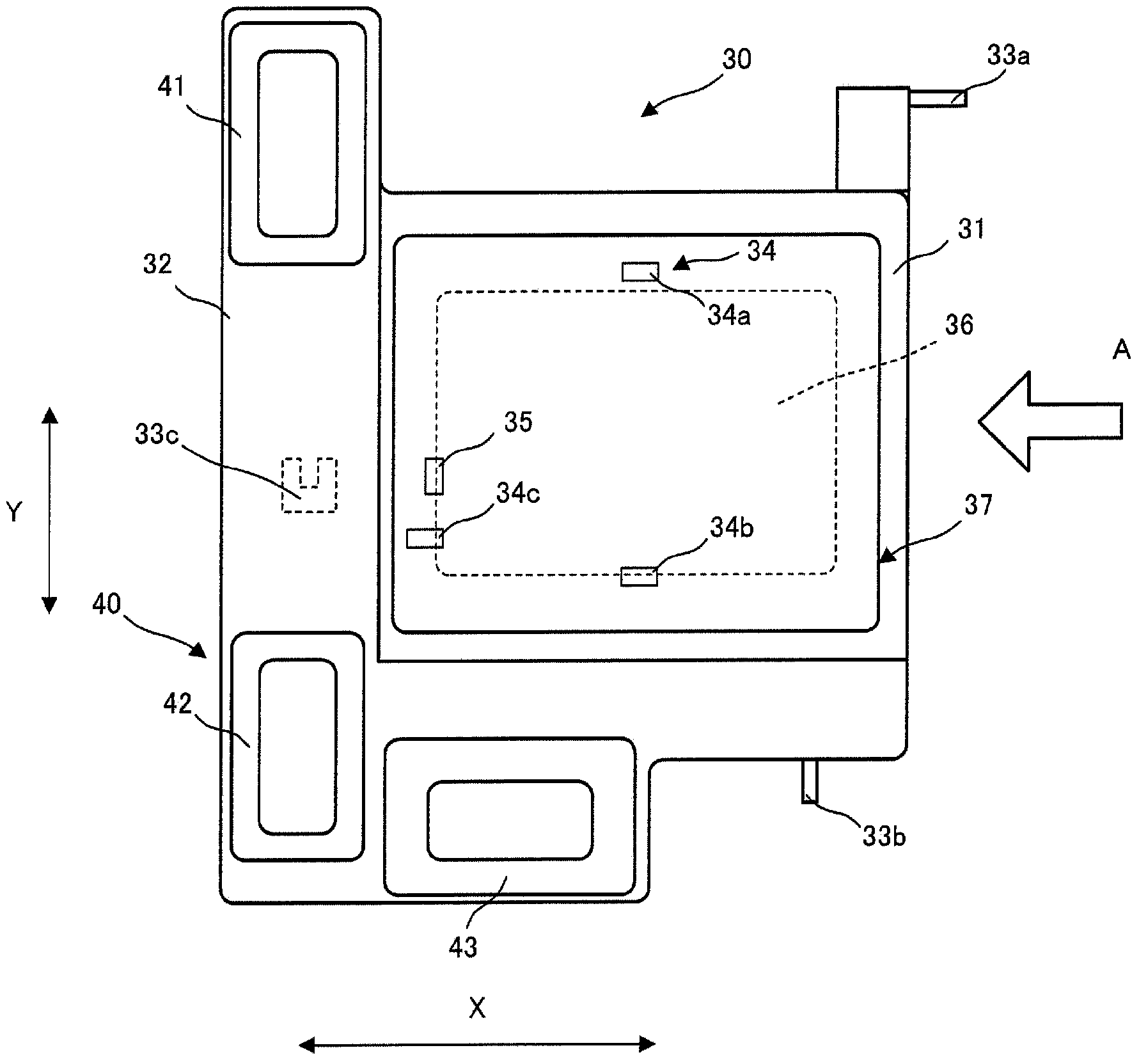
[0058] figure 1 It is a figure which shows the image shake correction apparatus 1 before assembly of this embodiment.

[0059] The image shake correction device 1 as the movable member control device of the present embodiment has: a base portion 10 as a base portion; a movable portion 30 movably supported on the base portion 10; and a magnet support portion 50, It is arranged on the opposite side of the base part 10 with respect to the movable part 30 and is fixed to the base part 10.

[0060] The first permanent magnet group 20 is fixed to the base portion 10, and the second permanent magnet group 60 is fixed to the magnet support portion 50. The coil assembly 40 is fixed to the movable part 30. The first permanent magnet group 20 and the second permanent magnet group 60 are arranged to face each other at the magnetized parts of different poles to generate a magnetic field in the opposing space. The coil gro...


PUM


Abstract

The moving member control apparatus of the invention is characterized by comprising a base part 10, a moving part 30 capable of moving relatively with respect to the base part 10, a first driving portion 71 that applies driving force to the moving part 30, a second driving portion 72 that applies driving force to the moving part 30, a first instruction portion that gives an instruction to the first driving portion 71 about a displacement position or where to move, a second instruction portion that gives an instruction to the second driving portion 72 about a displacement position, a first position acquisition portion 34a that acquires a real position of the first driving portion 71, a second position acquisition portion 34b that acquires a real position of the second driving portion 72, a first deviation calculation portion that calculates a first deviation eX1 between a position rX1 instructed by the first instruction portion and a real position X1pos acquired by the first position acquisition portion 34a, a second deviation calculation portion that calculates a second deviation eX2 between a position instructed by the second instruction portion and a real position X2pos acquired by the second position acquisition portion 34b, a correction portion 2 that products a first correction signal rX1 and a second correction signal rX2 corrected for the first deviation and the second deviation, respectively, depending on a difference between the first deviation and the second deviation, and a control portion 3 that receives the first correction signal rX1 and the second correction signal rX2 to control driving the forces of the first driving portion and the second driving portion, respectively.

Description

technical field [0001] The present invention relates to a movable member control device capable of reliably displacing a movable member having an unbalanced structure, and an imaging device provided with the movable member control device. Background technique [0002] As an example of controlling a movable member, there is a camera shake correction device. As a prior art of a camera shake correction device, for example, the technology disclosed in Patent Document 1 exists. In this camera shake correction device, a pair of voice coil motors are respectively disposed in the X and Y directions of a movable part on which an imaging element is mounted, and corrects camera shake. The shake correction device disclosed in Patent Document 1 is equipped with a voice coil motor to apply a force to the position of the center of gravity of the movable part, so that the imaging element does not rotate during translational motion in the X and Y directions. [0003] However, since the voi...

Claims


Application Information

Patent Timeline
IPC IPC(8): G03B5/00
CPCG03B5/00G02B27/646G03B2205/0069G03B2205/0038H04N23/687
Inventor 下山真雅石川隆志西原林太郎
Owner 奥之心数字科技株式会社
Why Eureka
Try Eureka