Air cylinder cover water draining sleeve water feeding hole sand core tenon and mounting technique thereof

A cylinder head and tenon technology, which is applied in the field of tenon technology design of the water jacket sand core under the cylinder head, can solve the problems such as the deformation of the water jacket core under the cylinder head, achieve the effect of preventing the deformation of the sand core and improving the assembly positioning accuracy

Active Publication Date: 2014-12-17
GUANGXI YUCHAI MASCH CO LTD
View PDF6 Cites 4 Cited by
  • Summary
  • Abstract
  • Description
  • Claims
  • Application Information

AI Technical Summary

Problems solved by technology

[0003] The purpose of the present invention is to solve the problem of deformation of the water jacket core under the cylinder head after the core is assembled. In addition, this patent has the advantages of reducing the casting edge, preventing errors in the core assembly, and improving the assembly and positioning accuracy of the sand core.

Method used


Image

  • Air cylinder cover water draining sleeve water feeding hole sand core tenon and mounting technique thereof
  • Air cylinder cover water draining sleeve water feeding hole sand core tenon and mounting technique thereof

Examples


Embodiment 1

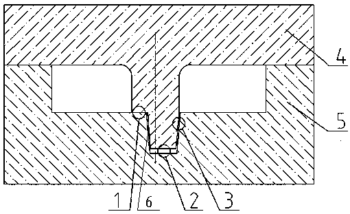
[0017] Example 1, the lower water jacket sand core (4) is installed on the chassis core (5), the non-conforming tenon (9) under the tenon (8) is put into the concave tenon pit (7), and the non-conforming tenon (9) is placed outside The diameter is an inverted cone with a slope distance (6), the concave tenon pit (7) is an inverted cone circle, and the outer diameter of the tenon head (9) to the side wall of the concave tenon pit (7) is the third gap (3), which is non-conformal There is a second gap (2) between the bottom surface of the tenon (9) and the bottom surface of the concave tenon (7), and there is a second gap (2) between the tenon (8) and the non-conforming tenon (9). a gap (1).

Embodiment 2

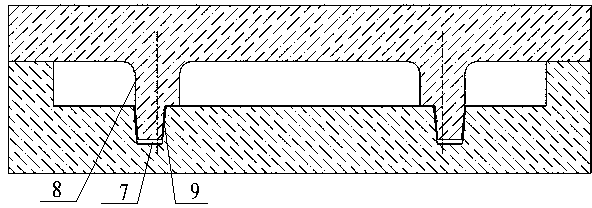
[0018] Example 2, a tenon for the sand core of the upper water hole of the lower water jacket of the cylinder head, including the first gap, the second gap, the third gap, the sand core of the lower water jacket, the chassis core, the slope distance, the concave tenon pit, the tenon head, and the non-conforming The tenon is characterized in that the lower water jacket sand core (4) is above the chassis core (5), the tenon head (8) of the lower water jacket sand core (4) is inserted into the concave tenon pit (7) of the chassis core (5), and the tenon head ( 8) The contact part of the tenon pit (7) is a non-conforming tenon (9), and the non-conforming tenon (9) is made in conjunction with the concave hole of the tenon pit (7), and the non-conforming tenon (9) of the tenon (8) ) into the tenon head pit (7), the gap between it and the pit wall is that the first gap (1) is 0mm, the second gap (2) is 0-5mm, and the third gap (3) is 0.1-1.0mm, The slope distance (6) is 5-30 mm...


PUM


Abstract

The invention discloses an air cylinder cover water draining sleeve water feeding hole sand core tenon and a mounting technique of the tenon. The tenon is characterized in that a water draining sleeve sand core is arranged on a chassis core, convex tenons of the water draining sleeve sand core are inserted in concave tenon pits of the chassis core, non-following tenons are arranged on the contact portions of the convex tenons and the concave tenon pits, the non-following tenons are made in cooperation with concave holes of the concave tenon pits, when the non-following tenons of the convex tenons are arranged in the concave tenon pits, first clearances, second clearances, third clearances, slope distances and the non-following tenons are formed in the clearances between the non-following tenons and the pit walls, the length of the non-following tenons is more than 1/2 of that of the convex tenons, the convex tenons and the non-following tenons are round, and the concave convex pits are round. The technique has the advantages that casting burrs are reduced, core assembling mistake prevention can be achieved, the assembling and positioning precision of the sand core can be improved, and the technique is suitable for the process design of various air cylinder cover water draining sleeve water feeding hole sand core tenons.

Description

technical field [0001] The patent of the present invention relates to a process design method for the tenon of the water hole on the sand core of the water jacket under the cylinder head. Background technique [0002] The shape of the tenon of the upper water hole of the lower water jacket of the traditional cylinder head is designed as a round core along with the shape of the upper water hole. figure 1 There is a gap at the second gap in the height direction. After the upper water jacket core and the chassis core are assembled, the upper water jacket core is deformed under the action of gravity, and the gap at the second gap at position 2 becomes smaller, so that the entire water jacket core is partially As the sand block moves down, the wall thickness formed by the upper water jacket core and the chassis core will become thinner, eventually resulting in uneven local wall thickness of the casting. For example, the theoretical wall thickness of the process design for the co...

Claims


Application Information

Patent Timeline
Patent Type & Authority Applications(China)
IPC IPC(8): B22C9/10
Inventor 廉振文张浩李章立黎武新陈祖礼
Owner GUANGXI YUCHAI MASCH CO LTD
Why Eureka
Try Eureka