
System and method for operating an engine

一种发动机系统、发动机的技术,应用在发动机元件、机器/发动机、装料系统等方向,能够解决发动机排放和燃烧稳定性退化等问题,达到提高燃料经济性、减少氮氧化物排放、降低可能性的效果

Active Publication Date: 2014-12-17
FORD GLOBAL TECH LLC
View PDF6 Cites 0 Cited by
  • Summary
  • Abstract
  • Description
  • Claims
  • Application Information

AI Technical Summary

Problems solved by technology

Therefore, when the engine changes from an operating condition in which a higher concentration of cooled EGR is supplied to the engine cylinders to a condition in which a lower concentration of cooled EGR is supplied to the engine cylinders, engine emissions and combustion stability may degrade

Method used


Image

  • System and method for operating an engine
  • System and method for operating an engine
  • System and method for operating an engine

Examples


Embodiment Construction

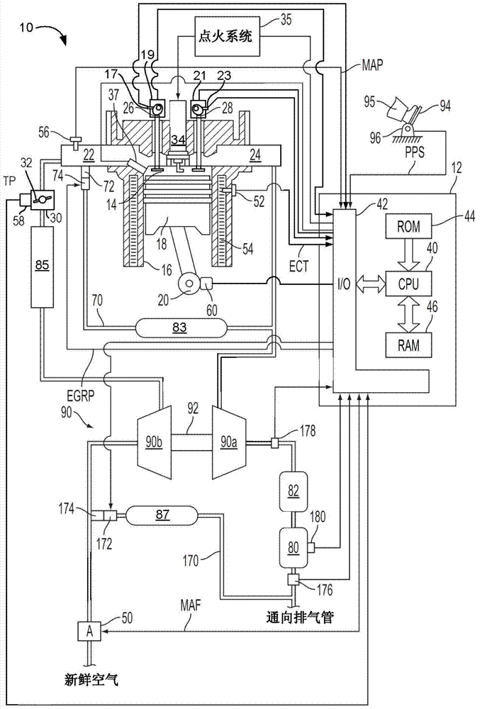
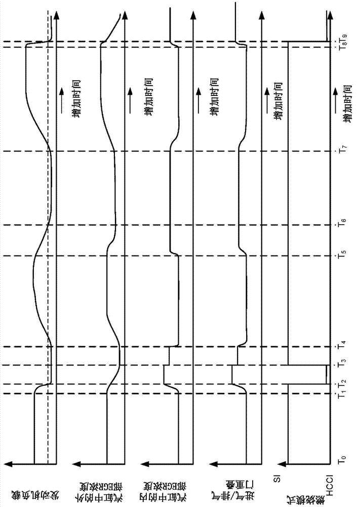
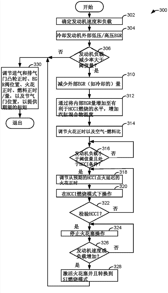
[0011] This description relates to transitioning the engine between engine loads. figure 1 One example system for providing power to propel a vehicle is shown. The system incorporates an engine that can be operated at lower or higher engine loads depending on driver demand or desired engine torque. The system includes a controller having non-transient commands for operating the engine in a spark ignition or homogeneous charge compression ignition combustion mode. figure 2 An example engine operating sequence is shown in which the engine combustion mode is changed to reduce the concentration of cooled external EGR in the engine cylinders so that combustion stability may be improved. image 3 is used to switch between spark ignition and homogeneous charge compression ignition combustion modes figure 1 Flowchart of an example method for the engine in .

[0012] figure 1 An example of a gasoline direct injection engine system, generally indicated at 10 , is shown. Specifical...


PUM


Abstract

A method for operating an engine is disclosed. In one example, internal EGR is increased during conditions where cooled EGR is at a higher concentration during a decreasing engine load so that homogeneous compression ignition may be initiated at lower engine loads.

Description

technical field [0001] This application relates to the field of internal combustion engines. In particular, it relates to the field of operating an internal combustion engine and transitioning the engine from a higher engine load condition to a lower engine load condition. Background technique [0002] Engine systems may incorporate exhaust gas recirculation (EGR) to improve engine operation. For example, EGR may reduce engine emissions (eg, nitrogen oxides) and increase engine efficiency by reducing engine pumping work. In some examples, external EGR (eg, EGR routed between the exhaust system and the engine intake system) may be cooled to further reduce engine NOx and reduce the risk of engine knock at higher engine loads possibility. Cooling the EGR further reduces cylinder firing temperatures, thereby reducing the formation of nitrogen oxides and auto-ignition of the exhaust. However, at lower engine loads, cooled EGR may degrade combustion stability and cause the pos...

Claims


Application Information

Patent Timeline
Patent Type & Authority Applications(China)
IPC IPC(8): F02M25/07
CPCF02M25/07F02M26/05F02M26/06
Inventor G·苏尔尼拉E·W·柯蒂斯D·J·斯泰尔斯S·麦卡帕迪
Owner FORD GLOBAL TECH LLC
Learn More