

Water tank used for heat pump hot water heater
A heat pump water heater and hot water technology, which is applied in fluid heaters, lighting and heating equipment, etc., can solve the problems of large volume and low hot water output efficiency, and achieve the effect of improving the hot water output rate
- Summary
- Abstract
- Description
- Claims
- Application Information
AI Technical Summary
Problems solved by technology
Method used
Image

Examples
Embodiment 1
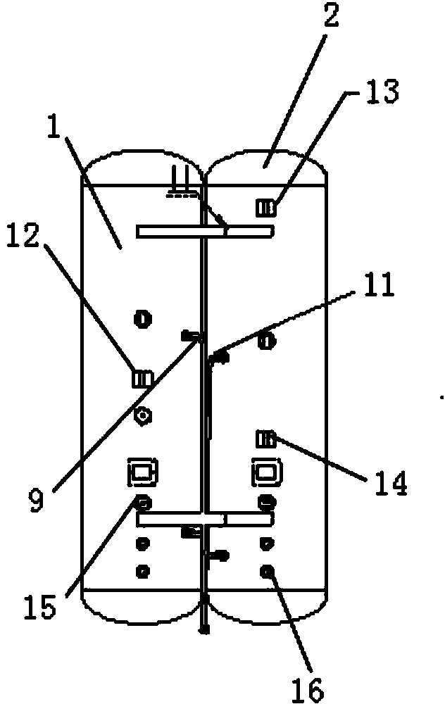
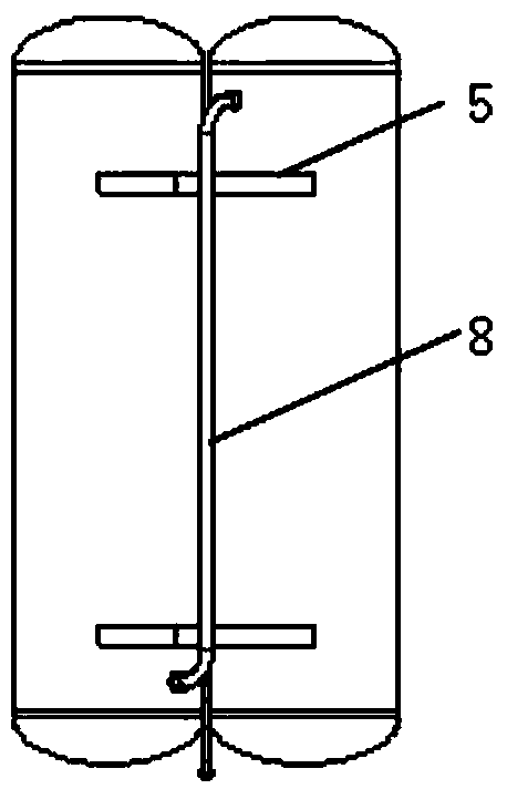
[0029] The water tank in this embodiment includes an inner tank, an outer shell and a heat exchange coil, the heat exchange coil is built in the inner tank, and the inner tank is arranged in the outer shell, as Figure 1 ~ Figure 3 As shown, the inner tank is a double inner tank, and the double inner tank includes a hot water outlet inner tank 1 on the right side and a cold water inlet inner tank 2 on the left side, and the hot water outlet inner tank The bottom of 1 is provided with a hot water outlet 3, and the bottom of the cold water inlet tank 2 is provided with a cold water inlet 4, and the hot water outlet tank 1 and the cold water inlet tank 2 are connected by an inner tank connecting piece 5, The hot water outlet liner 1 is provided with a first heat exchange coil 6 , and the cold water inlet liner is provided with a second heat exchange coil 7 .
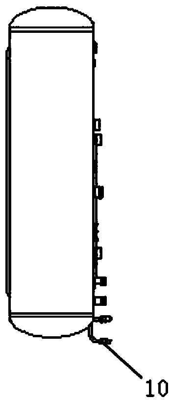
[0030] The first end of the first heat exchange coil 6 communicates with the outside of the inner tank with the first end...
Embodiment 2
[0035] Such as Figure 4 ~ Figure 7 As shown, in this embodiment, on the basis of Embodiment 1, water temperature probes are arranged on the outside of the cold water inlet inner tank 2 on the left side and the hot water outlet inner tank 1 on the right side, and A first water temperature probe 12 is arranged in the middle of the surface, and a second water temperature probe 13 and a third water temperature probe 14 are respectively arranged in the middle and upper parts of the outer surface of the hot water outlet liner. At the same time, a first electric heating tube 15 and a second electric heating tube 16 are correspondingly provided in the cold water inlet inner tank and the hot water outlet inner tank respectively.
[0036] Through the first water temperature probe 12, the second water temperature probe 13 and the third water temperature probe 14, the water temperature at different positions of the inner tank is displayed in real time. During the hot water use, when the ...
Embodiment 3
[0038] Such as Figure 7 As shown, on the basis of Embodiment 2, this embodiment is also provided with a hot water outlet pipe 17, the head end of the hot water outlet pipe 17 is located on the top of the hot water outlet liner 1, and the hot water outlet pipe 17 The tail end communicates with the hot water outlet 3.
[0039]The hot water that flows from the top of the left cold water inlet liner 2 into the bottom of the right hot water outlet liner is reheated by the first heat exchange coil in the right hot water outlet liner, and the heated high-temperature hot water , flows out from the top of the hot water outlet liner through the hot water outlet pipe. The hot water outlet pipe 17 stretches to the top of the hot water outlet liner 1 to take water to ensure that the hot water outlet 3 goes out of high-temperature hot water, further improving the water outlet efficiency of the hot water.
[0040] In addition, the bottoms of the cold water inlet inner tank and the hot wat...
PUM
 Abstract
Description
Claims
Application Information